
Circuit and method for soft start of a switching regulator from a residual voltage

a switching regulator and residual voltage technology, applied in the direction of electric variable regulation, process and machine control, instruments, etc., can solve the problems of wasting remaining electric charges, affecting the performance of soft start, and only being able to use the soft start circuit in buck pulse width modulation

Active Publication Date: 2008-10-02
RICHTEK TECH
View PDF3 Cites 26 Cited by
  • Summary
  • Abstract
  • Description
  • Claims
  • Application Information

AI Technical Summary

Benefits of technology

[0005]An object of the present invention is to provide a circuit and method for soft start of a switching regulator form a residual voltage. Specifically, the inventive circuit and method may prevent a reverse current during the soft start period, and is suitable for all types of switching regulators.

Problems solved by technology

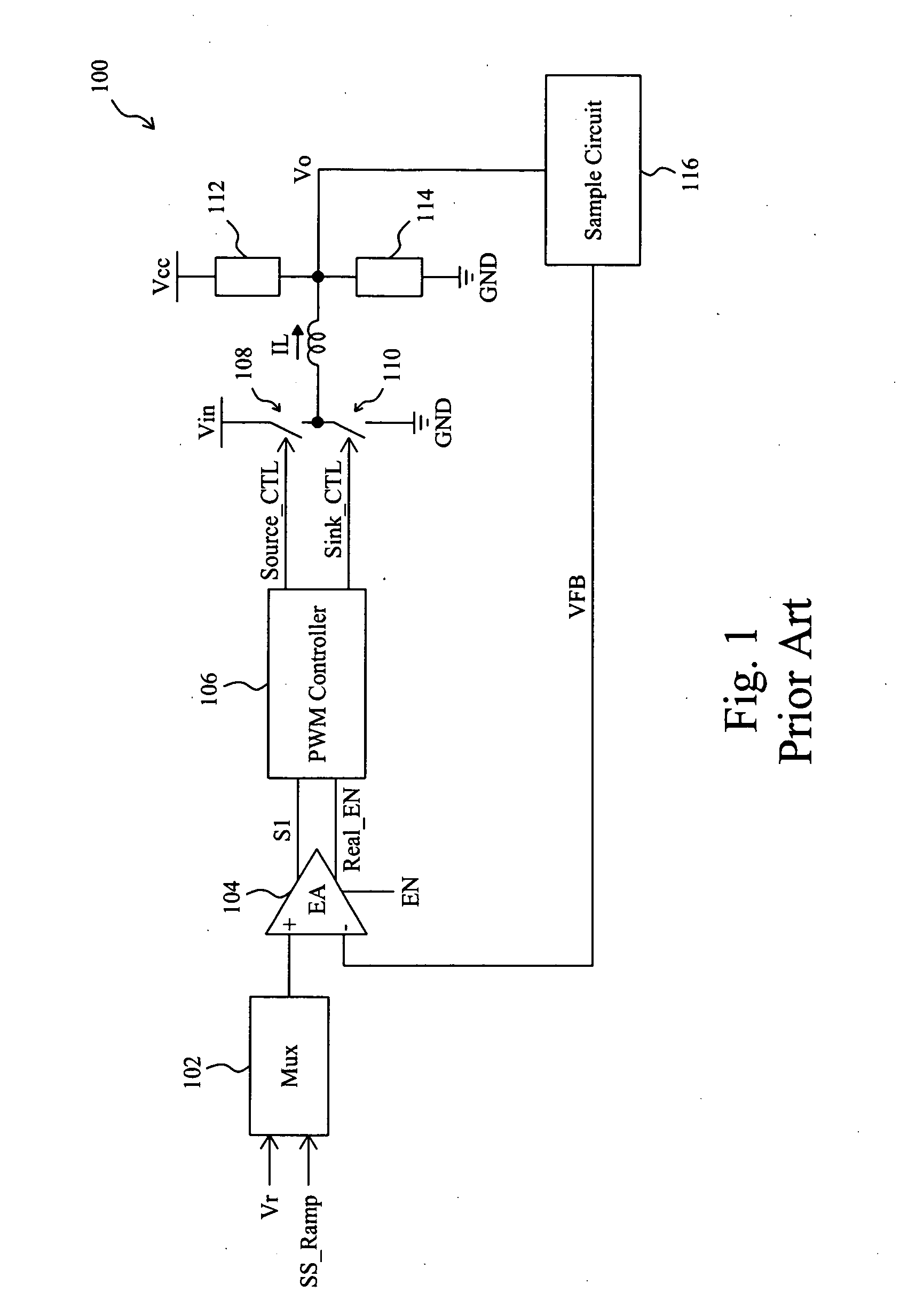
However, there may be some electric charges remaining on the output terminal of the system after the last operation of the system, which makes the output voltage of the system not be zero at the beginning of the next start-up.
Conventionally, the soft start of a system always releases the remaining electric charges on the output terminal of the system in advance and then charges it again, which wastes those remaining electric charges.
However, this soft start circuit can be only used in a buck pulse width modulation (PWM) circuit.
However, this soft start circuit needs an extra capacitor as the soft start capacitor, and the sawtooth wave at beginning to be compared with the output voltage has a RC discharge curve, which is disadvantageous to the performance of the soft start.

Method used


Image

  • Circuit and method for soft start of a switching regulator from a residual voltage
  • Circuit and method for soft start of a switching regulator from a residual voltage
  • Circuit and method for soft start of a switching regulator from a residual voltage

Examples


first embodiment

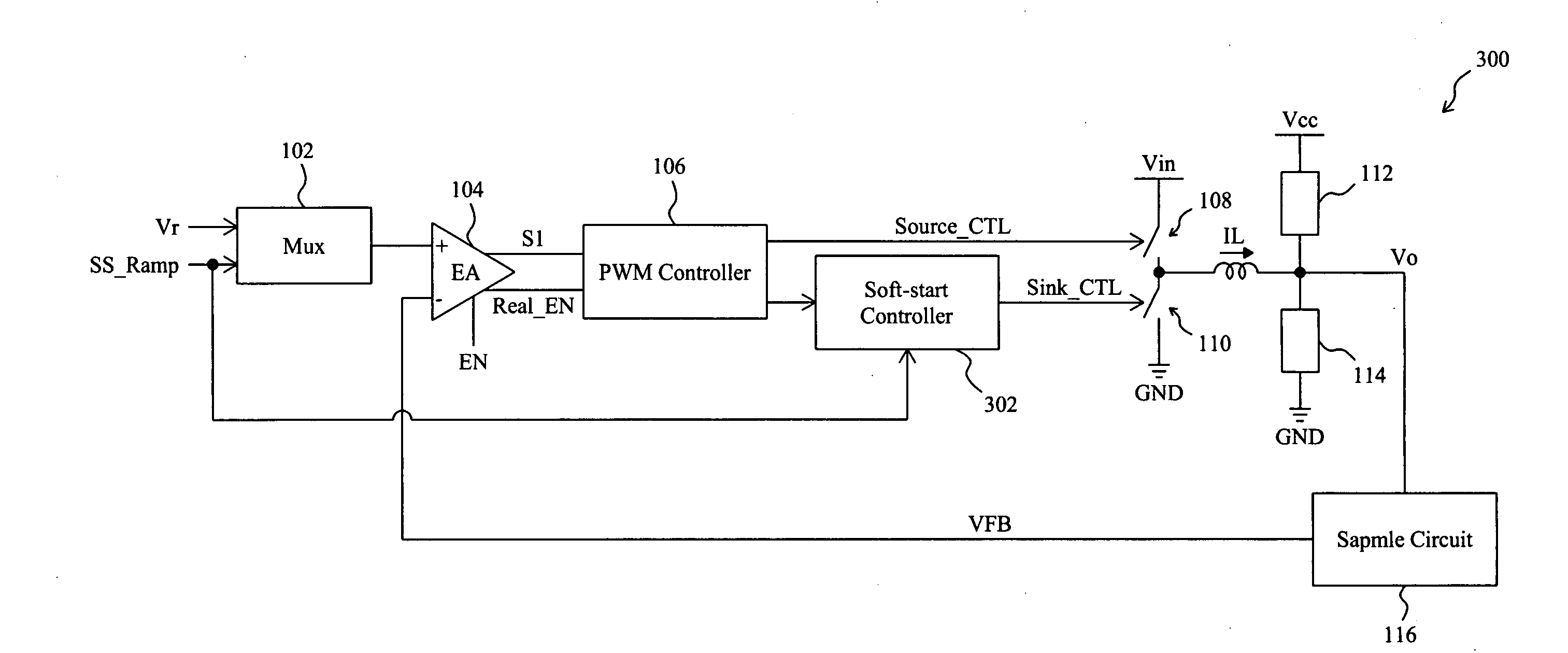
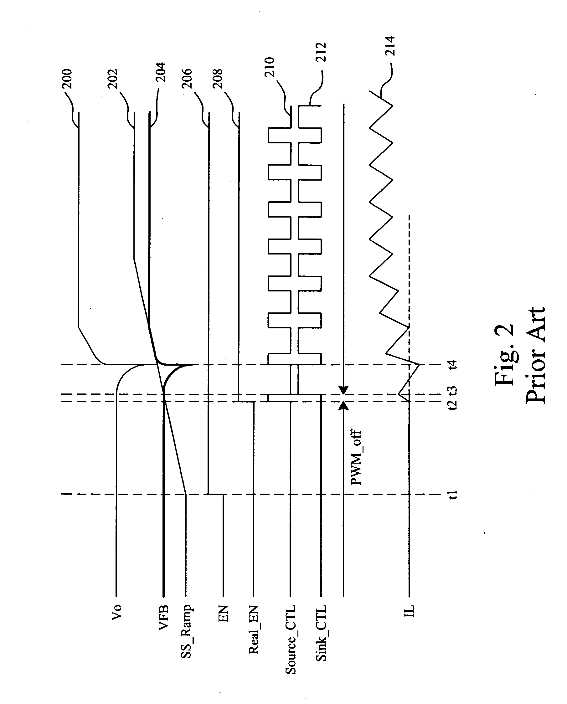
[0013]FIG. 3 shows a first embodiment according to the present invention, and FIG. 4 is a waveform diagram showing the signals in the circuit of FIG. 3. Referring to FIGS. 3 and 4, waveform 400 represents the output voltage Vo of the synchronous switching regulator 300, waveform 402 represents the ramp signal SS_Ramp for soft start of the synchronous switching regulator 300, waveform 404 represents the feedback signal VFB, waveform 406 represents the enable signal EN for the error amplifier 104, waveform 408 represents the enable signal Real_EN for the PWM controller 106, waveform 410 represents the high side signal Source_CTL, waveform 412 represents the low side signal Sink_CTL, and waveform 414 represents the inductor current IL. In the synchronous switching regulator 300, the high side switch 108 and the low side switch 110 are connected between the power input Vin and ground GND, to be switched to produce the output voltage Vo and the inductor current IL to supply for two loads...

second embodiment

[0014]FIG. 5 shows a second embodiment according to the present invention, with the same waveform diagram shown in FIG. 4. In this synchronous switching regulator 500, the operation is the same as that of the synchronous switching regulator 300 of FIG. 3, except that the high side signal Source_CTL is also connected to a soft start controller 502, and the soft start controller 502 counts the number of switching times of the high side switch 108 by monitoring the high side signal Source_CTL, in order to determine when to stop blocking the low side signal Sink_CTL. As did by the soft start controller 302 in the synchronous switching regulator 300 of FIG. 3, the soft start controller 502 also blocks the low side signal Sink_CTL for a period of time after the synchronous switching regulator 500 is enabled, such that the synchronous switching regulator 500 operates in an asynchronous mode during this period of time. When the number of switching times of the high side switch 108 during th...


PUM


Abstract

For soft start of a switching regulator, the output voltage of the switching regulator is fed back to be compared with a ramp signal, in order to trigger a comparison signal when the ramp signal rises up to reach the feedback signal, to enable the switching regulator such that the output voltage changes from a residual voltage toward a target value. The low side switch of the switching regulator is kept off for a period of time after the switching regulator is enabled, so as to prevent a reverse current during the soft start period.

Description

FIELD OF THE INVENTION[0001]The present invention is related generally to a circuit and method for soft start of a switching regulator and, more particularly, to a circuit and method for soft start of a switching regulator from a residual voltage.BACKGROUND OF THE INVENTION[0002]In many systems, soft start function is provided for monotonic start-up of the systems, to reduce the impact to the systems during the start-up and thereby avoid overload to some elements thereof and over voltage of the systems. For further detailed information about soft start, readers may refer to U.S. Pat. No. 6,552,517 to Ribellino et al. In conventional soft start methods, the system always starts up from a zero voltage. However, there may be some electric charges remaining on the output terminal of the system after the last operation of the system, which makes the output voltage of the system not be zero at the beginning of the next start-up. Conventionally, the soft start of a system always releases t...

Claims


Application Information

Patent Timeline
Patent Type & Authority Applications(United States)
IPC IPC(8): G05F1/00
CPCH02M1/36H02M3/1588Y02B70/1466Y02B70/10Y10S323/901
Inventor CHEN, ISAAC Y.TANG, CHIEN-FU
Owner RICHTEK TECH
Learn More