
Method and apparatus for membrane deposition

a technology of membrane coating and honeycomb, applied in the field of membrane coating deposition in honeycomb channels, can solve the problems of difficult to overcome, the above methods are not effective in coating such channels using reactive processes, and the process is not applicable to the membrane coating process

Active Publication Date: 2008-10-02
CORNING INC
View PDF8 Cites 33 Cited by
  • Summary
  • Abstract
  • Description
  • Claims
  • Application Information

AI Technical Summary

Benefits of technology

[0006]The present invention meets these and other needs by providing a method and apparatus for applying a uniform membrane coating to a substrate, such as a honeycomb structure, having a plurality of through-channels. The method includes providing a liquid precursor comprising membrane-forming materials to the substrate and applying a pressure differential across the substrate. The pressure differential causes the liquid precursor to travel

Problems solved by technology

However, the application of membrane coatings to multiple small sized (≦3 mm diameter) channels in a monolithic substrate or support presents challenges that are difficult to overcome using the previously mentioned methods.
In addition, the above methods are not effective in coating such channels using reactive processes, such as electroless plating, hydrothermal synthesis, and the like.
Whereas wash coating has been used to deposit catalyst layers on honeycomb substrates having small channels and high densities, this process is not applicable to the membrane coating process for several reasons.
First, wash coating typically results in a coating layer having a number of cracks and a thickness that is greater than that desired for membrane films.
Secondly, the length of the honeycomb structure that can be coated by wash coating is limited to about 6 inches (about 15 cm).
Presently available coating techniques are unable to provide uniform membrane coatings for small channels of honeycomb structures of longer length.

Method used


Image

  • Method and apparatus for membrane deposition
  • Method and apparatus for membrane deposition
  • Method and apparatus for membrane deposition

Examples


example 1

Physical Deposition of Porous α-Alumina Membrane onto Monolithic Channels

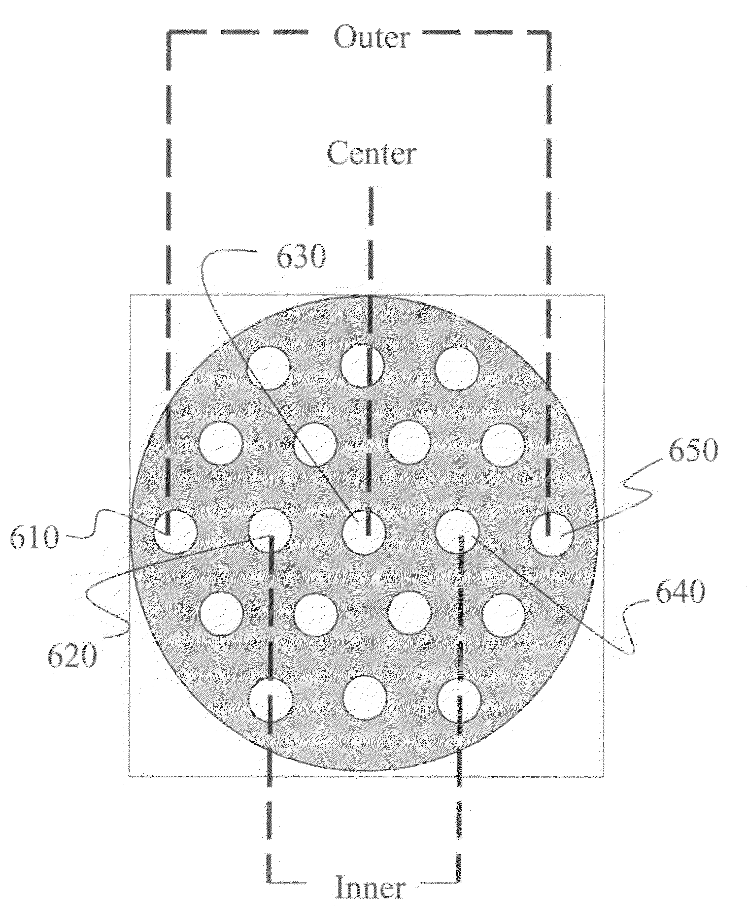
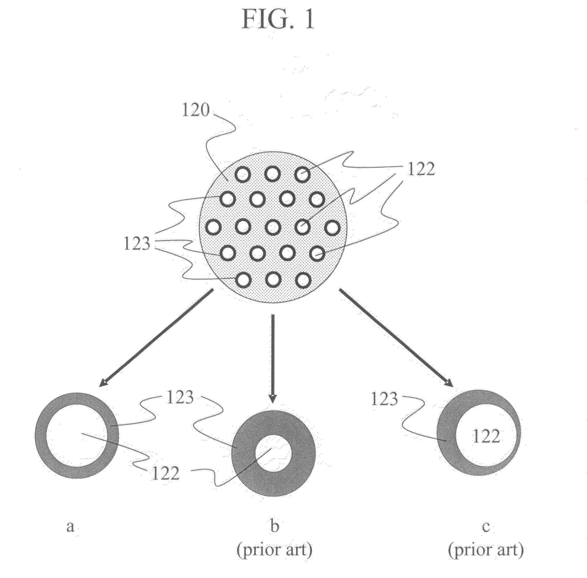
[0052]Unless otherwise specified, monolithic substrate (also referred to herein as “monolithic supports”) made of α-alumina, each having an outer diameter ranging from 8.7 mm to 9.2 mm and a length of about 150 mm, were used in this example. Each monolithic support had 19 through-channels uniformly distributed over the cross-sectional area of the monolithic support. The average diameter of the through-channels was 0.75 mm.

[0053]The monolithic support was mounted into the apparatus shown in FIG. 3, described hereinabove. A water-based coating solution 331 containing α-alumina particles, a dispersant, and a polymeric anti-cracking agent was used as the liquid precursor. The coating solution 331 was placed inside a beaker 330. The top of beaker 330 was open to air, and the contents of beaker 330 were exposed to atmospheric pressure.

[0054]A suction tube 332 was immersed in coating solution 331 and connected to the...

example 2

Microfiltration of Deposited α-Alumina Membrane

[0058]Two sets of membranes formed in the manner described in Example 1 were used to test the filtration of skim milk / water mixtures. One set of membranes was formed using a coating solution comprising 4 vol % α-alumina (Sample 2A), and a second set of membranes was formed using a coating solution comprising 6 vol % α-alumina (Sample 2B). The microfiltration performance of the α-alumina membranes is shown in Table 1.

[0059]Less than 0.1% of the protein particles in the skim milk / water mixture had a size of less than 0.068 μm, whereas 99.9% of the protein particles had a size of less than 0.409 μm, as measured by a Nanotrac™ light scattering size analyzer.

[0060]The filtration function of a membrane is gauged by the turbidity number (NTU) of the membrane. NTU is a measure of the amount of particulate passes through a membrane. A NTU value of less than 12 is considered acceptable for commercially available 200 nm membranes.

[0061]Both sets ...

example 3a

Electroless Deposition of Pd Thin Film Membrane Using Method and Apparatus Described Herein

[0062]This example illustrates the chemical deposition of a membrane film using the method and apparatus described herein.

[0063]Palladium and palladium alloys with copper or silver are well known as membrane materials for hydrogen separation. These membranes have both high flux and high selectivity to hydrogen permeation at temperatures above 250° C.

[0064]An electroless plating technique was used in the instant method to deposit palladium membrane coatings on monolithic supports. The liquid precursor or coating solution comprised aqueous-based precursors. For the electroless plating of palladium, the aqueous-based precursors included: PdCl2 (0.04 M); Na2EDTA·2H2O) (0.2 M), NH3.H2O (25 wt. %) (600 ml / L), and N2H4.H2O (80 wt. %) (1.2 ml / L). The palladium membrane was synthesized by the following chemical reaction on the support surface:

2Pd(NH3)42++N2H4+4OH−2Pd+N2+8NH3+4H2O

[0065]Deposition of pa...


PUM

PropertyMeasurementUnit
Pressureaaaaaaaaaa
Pressureaaaaaaaaaa
Diameteraaaaaaaaaa

Abstract

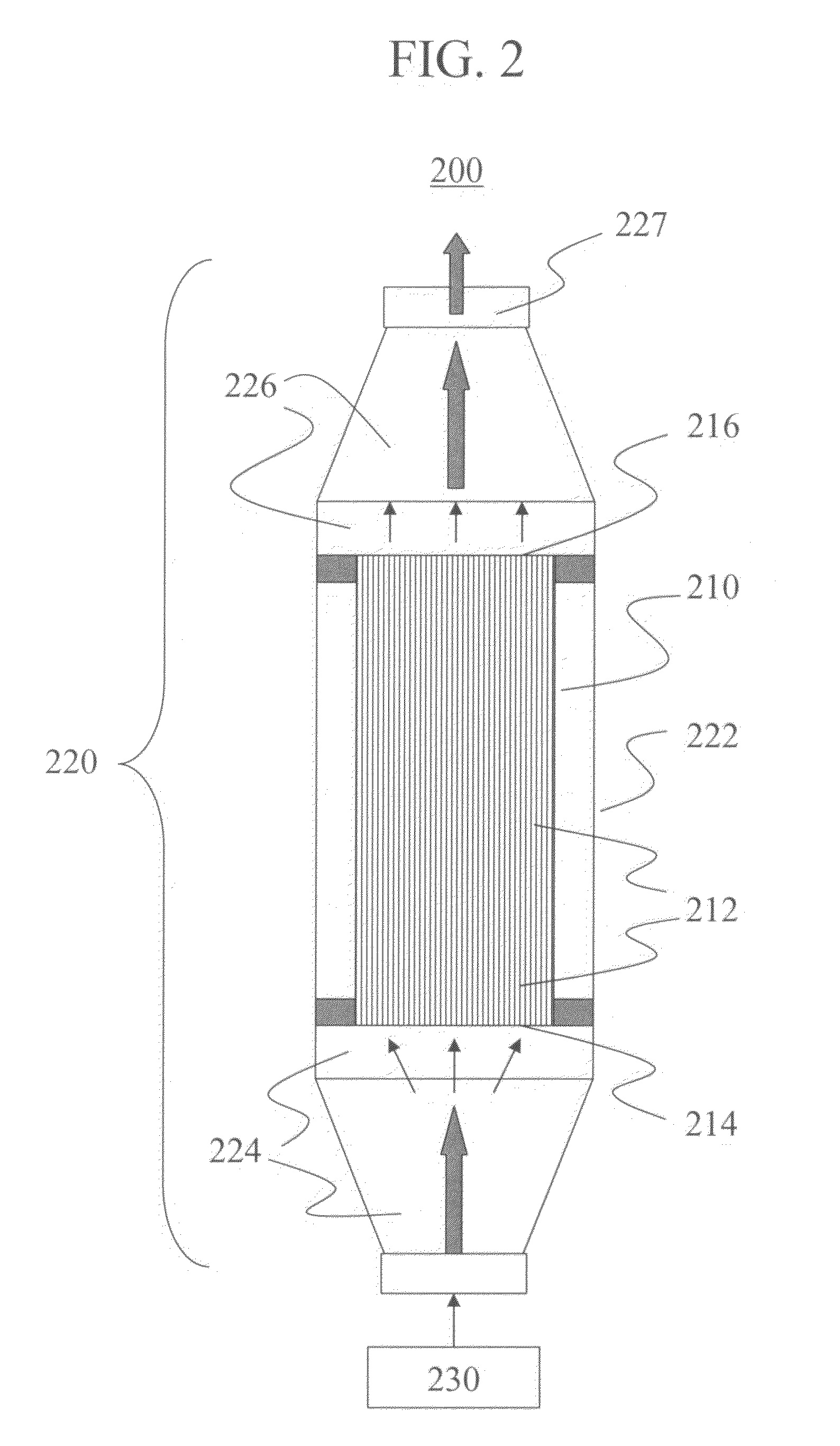
A method and apparatus for applying a uniform membrane coating to a substrate, such as a honeycomb structure, having a plurality of through-channels, wherein the through-channels have an average diameter of less than or equal to 3 mm. The method includes providing a liquid precursor comprising membrane-forming materials to the substrate and applying a pressure differential across the substrate. The pressure differential causes the liquid precursor to travel uniformly through the through-channels, depositing the membrane-forming materials on the walls of the through-channels and forming the membrane on the walls of the through-channels. The apparatus includes a chamber capable of holding the substrate and of maintaining a pressure differential across the plurality of through-channels.

Description

BACKGROUND OF INVENTION[0001]The invention relates to the deposition of coatings in channels. More particularly, the invention relates to the deposition of membrane coatings in honeycomb channels having small diameters. Even more particularly, the invention relates to a method and apparatus for depositing membrane coatings in honeycomb channels having small diameters.[0002]A variety of coating methods, including dip-coating, slip casting, and spin coating have been used to deposit layers of materials—particularly membrane materials—on porous substrates or support structures. Such methods work well for coating flat surfaces, external surfaces of tubular structures, or internal surfaces of large diameter tubes.[0003]However, the application of membrane coatings to multiple small sized (≦3 mm diameter) channels in a monolithic substrate or support presents challenges that are difficult to overcome using the previously mentioned methods. Such challenges include the introduction of visco...

Claims


Application Information

Patent Timeline
IPC IPC(8): B28B3/20B05C11/02C23C14/00
CPCB01D63/066B01D2323/42B01D67/0069B05C7/04B05D1/00B05D3/0493B05D7/22C04B38/0096C23C18/1216C23C18/1628C23C18/1644C23C18/1678C23C18/42B01D67/0046B01D63/061C04B35/00C04B38/0006
Inventor LIU, WEIFEKETY, CURTIS ROBERTST CLAIR, TODD P
Owner CORNING INC
Learn More