Cutting Insert for a Milling Cutter
a cutting insert and milling cutter technology, applied in the field of cutting inserts, can solve the problems of affecting the surface finish, exerting a high load on cutting,
- Summary
- Abstract
- Description
- Claims
- Application Information
AI Technical Summary
Benefits of technology
Problems solved by technology
Method used
Image
Examples
Embodiment Construction
[0036]The contents of aforementioned U.S. Pat. No. 6,336,776 are incorporated by reference to the extent necessary to understand the present invention.
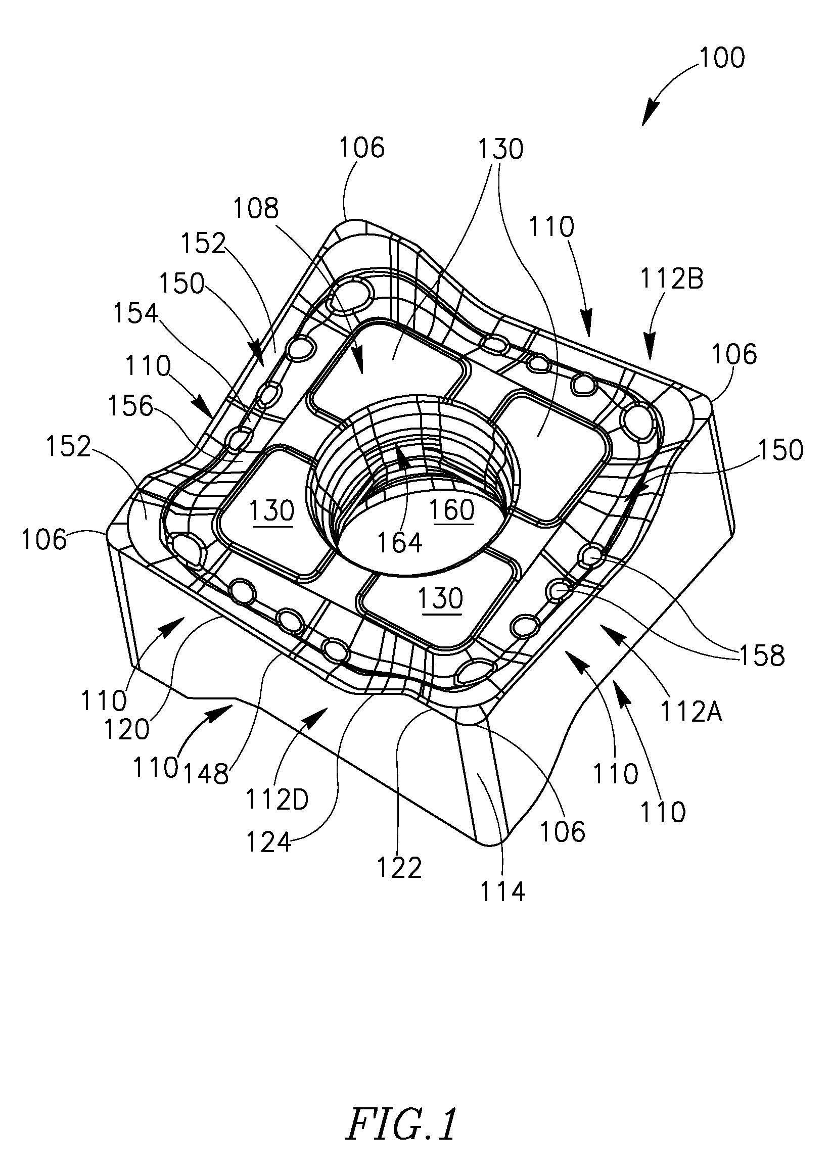
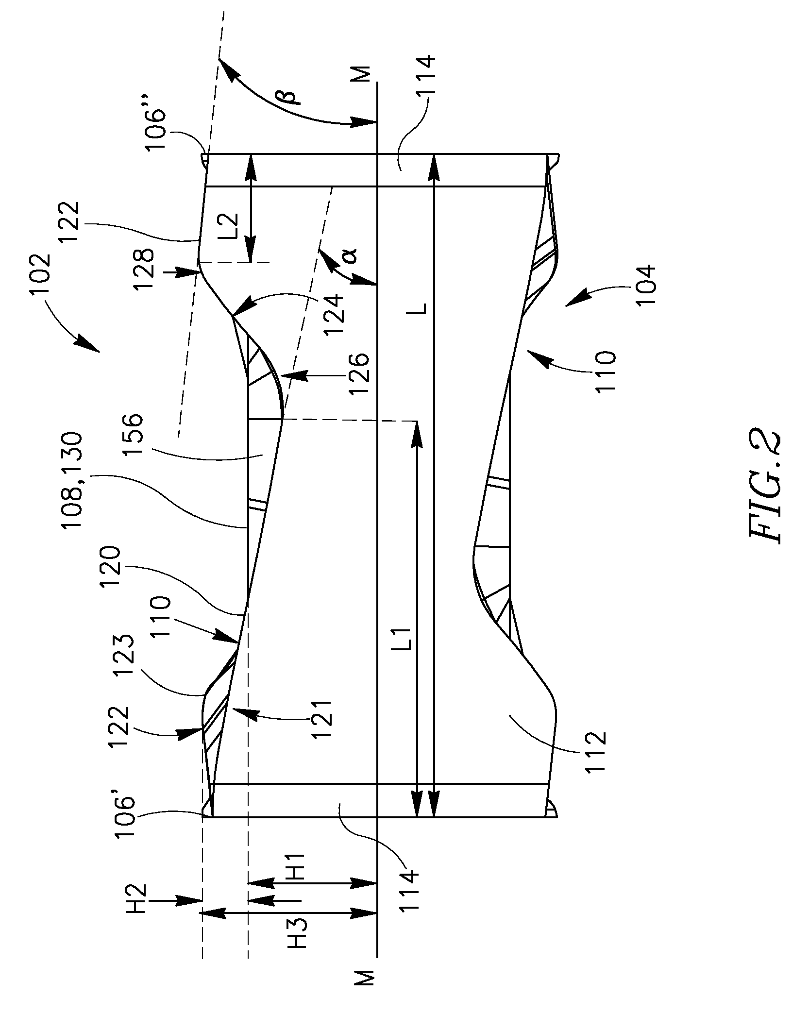
[0037]FIGS. 1-5 show one embodiment of a cutting insert 100 in accordance with the present invention. Cutting insert 100 is preferably formed from carbide or other material by pressing and sintering, injection molding, or other known manner.
[0038]Cutting insert 100 is double-ended (i.e., reversible) with each end being four-way indexable, providing a total of eight cutting positions. The insert's first end surface 102 and second end surface 104 face in opposite directions and are substantially square in an end view (see FIG. 3). Each end surface is provided with an associated abutment surface 108 in a central region thereof, and four associated insert corners 106. As seen in FIGS. 2 and 4, the insert corners 106 do not form the high points, in a side view of the cutting insert.
[0039]The cutting insert 100 has four side surfaces 112A, ...
PUM
| Property | Measurement | Unit |
|---|---|---|
| Angle | aaaaa | aaaaa |
| Cell angle | aaaaa | aaaaa |
| Cell angle | aaaaa | aaaaa |
Abstract
Description
Claims
Application Information
 - R&D
- Intellectual Property
- Life Sciences
- Materials
- Tech Scout
- Unparalleled Data Quality
- Higher Quality Content
- 60% Fewer Hallucinations
Browse by: Latest US Patents, China's latest patents, Technical Efficacy Thesaurus, Application Domain, Technology Topic, Popular Technical Reports.
© 2025 PatSnap. All rights reserved.Legal|Privacy policy|Modern Slavery Act Transparency Statement|Sitemap|About US| Contact US: help@patsnap.com


