
Honeycomb structure body and method for producing the same

Inactive Publication Date: 2008-09-25
NGK INSULATORS LTD
View PDF4 Cites 23 Cited by
  • Summary
  • Abstract
  • Description
  • Claims
  • Application Information

AI Technical Summary

Benefits of technology

[0007]The present invention has been made in view of such conventional circumstances and aims to provide a honeycomb structure capable of suitably be used for a filter for trapping particulate matter, such as a diesel particulate filter (DPF) and capable of detecting an accumulation amount of particulate matter easily with high accuracy when the honeycomb structure is used for a filter for trapping particulate matter.
[0031]A honeycomb structure of the present invention can suitably be used for a filter for trapping particulate matter, such as a diesel particulate filter (DPF) and can detect an accumulation amount of particulate matter easily with high accuracy when the honeycomb structure is used for a filter for trapping particulate matter, which enables to easily determine timing of the exchange or the regeneration treatment of the filter. In addition, a manufacturing method of the present invention enables to manufacture honeycomb structures as described above relatively easily and is suitable for mass production.

Problems solved by technology

However, in a filter for trapping particulate matter, there are many cases that pressure loss of a filter has hysteresis with respect to the accumulation amount of particulate matter, and it is often impossible to unambiguously detect the accumulation amount of particulate matter only from the pressure difference in discharged pressure between in front end of the filter and at the rear end of filter due to pressure loss of the filter.
For example, in a wall flow type ceramic filter (DPF) for trapping particulate matter discharged from a diesel engine, when temperature temporarily rises to a level where a catalyst coated inside pores of the filter becomes active after particulate matter is trapped at low temperature, the particulate matter accumulated inside the pores is oxidized and removed, and pressure loss decreases to a large extent due to oxidation and removal of a small amount of particulate matter in pores.
Therefore, a relation between the accumulation amount of particulate matter and pressure loss show hysteresis, and there arises a large difference in an amount of particulate matter even with the same pressure loss.
Therefore, in such a filter for trapping particulate matter, it is difficult to estimate the accumulation amount of particulate matter unambiguously, and, at present, when timing of the exchange or the regeneration treatment of filter is determined, the accumulation amount of particulate matter in a filter is estimated with employing the prediction of the generation amount of particulate matter from an engine depending on a driving period of time and driving conditions together with information on pressure loss to determine timing of the exchange or the regeneration treatment of filter from the estimated amount of accumulation.

Method used


Image

  • Honeycomb structure body and method for producing the same
  • Honeycomb structure body and method for producing the same
  • Honeycomb structure body and method for producing the same

Examples


example

[0111]Talc (mean particle diameter: 20 μm, powder having particle diameter of 75 μm or more: 4 mass %) , molten silica (mean particle diameter: 35 μm, powder having particle diameter of 75 μm or more: 0.5 mass %) , and aluminum hydroxide (mean particle diameter: 2 μm, powder having particle diameter of 75 μm or more: 0 mass %) were mixed together at a proportion of 37 mass % of talc, 19 mass % of molten silica, and 44 mass % of aluminum hydroxide to prepare a cordierite-forming material.

[0112]Next, to 100 parts by mass of the cordierite-forming material were added 20 parts by mass of graphite, 7 parts by mass of polyethylene telephthalate, 7 parts by mass of poly(methyl methacrylate), 4 parts by mass of hydroxypropylmethyl cellulose, 0.5 parts by mass of potash soap laurate, and 30 parts by mass of water, and they were mixed to give plasticity to the mixture. The raw material having plasticity was formed to obtain clay of a cylindrical shape by a vacuum kneader, and the clay was for...


PUM

PropertyMeasurementUnit
Electrical resistanceaaaaaaaaaa
Electrical conductoraaaaaaaaaa
Capacitanceaaaaaaaaaa

Abstract

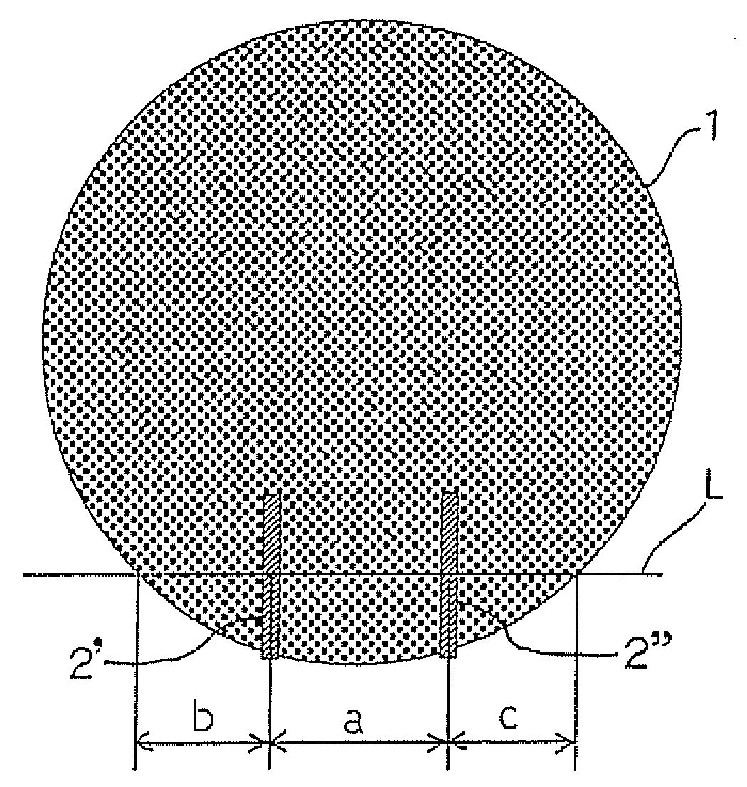
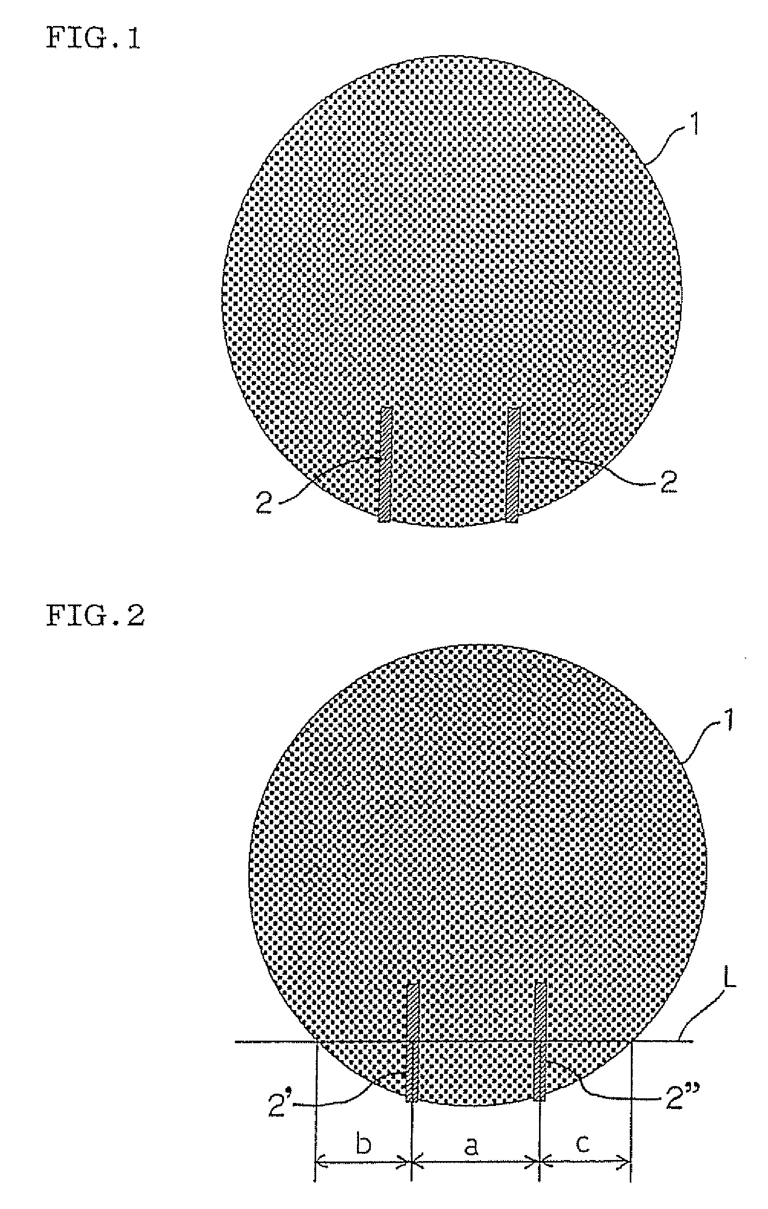
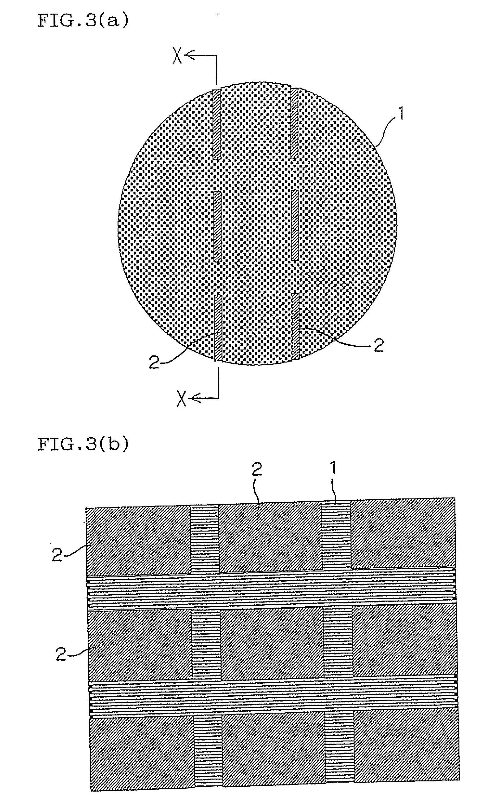
There is provided a honeycomb structure capable of suitably be used for a filter for trapping particulate matter, such as a diesel particulate filter (DPF) and capable of detecting an accumulation amount of particulate matter easily with high accuracy when the honeycomb structure is used for a filter for trapping particulate matter. The honeycomb structure 1 has a plurality of cells functioning as gas passages and partitioned and formed by the porous partition walls and has two or more electrodes therein.

Description

TECHNICAL FIELD [0001]The present invention relates to a honeycomb structure suitably usable for a filter for trapping particulate matter, such as a diesel particulate filter (DPF) and having electrodes and a method for manufacturing the honeycomb structure.BACKGROUND ART [0002]A representative means for purifying gas by trapping particulate matter in the gas is filtration with a filter. Examples of a material and a structure of a filter include a fiber layer, a ceramic form, and a metal form. In particular, as a material and a structure capable of reducing pressure loss, there is well known a wall-flow type one in which an end portion of each of the cells is alternately plugged in such a manner that the end faces of a honeycomb structure having a plurality of cells functioning as gas passages and being partitioned and formed by porous partition walls show a checkerwise pattern.[0003]In such a filter for trapping particulate matter, it is necessary to exchange the filter for a new o...

Claims


Application Information

Patent Timeline
IPC IPC(8): B01D46/50B32B3/12B29C35/02
CPCB01D46/0078B01D46/2418B01D2279/30F01N3/0222F01N9/002Y10T428/24157F01N2330/18F01N2560/14Y02T10/20Y02T10/47Y10T428/24149F01N2330/06Y02T10/12Y02T10/40B01D46/785F01N3/02B01D39/20F01N3/10B01D46/42
Inventor KATSUYAMA, KYOSUKEMIYASHITA, TAKEYAKITOH, KENSHINMIYAIRI, YUKIO
Owner NGK INSULATORS LTD
Learn More