
Communication method between at least one subscriber station and at least two base stations

Inactive Publication Date: 2008-09-18
INTERDIGITAL CE PATENT HLDG
View PDF10 Cites 6 Cited by
  • Summary
  • Abstract
  • Description
  • Claims
  • Application Information

AI Technical Summary

Benefits of technology

[0005]More particularly, the purpose of the invention is to enable the transmission and / or reception of data by at least one wireless station intended for or coming from relay stations, with a guaranteed quality of service and more specifically with an absence of cutting off of the communication (namely, with no loss of packets sent or having to be received by the wireless station or stations) under normal conditions of use.

Problems solved by technology

Such an architecture does not enable Quality of Service (or QoS) to be managed effectively enough for some applications.
Nevertheless, the techniques implemented in the Wimax networks do not enable a quality of service to be guaranteed for all the applications, for example for video type communications, data being transmitted by wireless cameras moving around in noisy radio-frequency environments, subject to interference or disturbed by obstacles creating signal losses or echoes.

Method used


Image

  • Communication method between at least one subscriber station and at least two base stations
  • Communication method between at least one subscriber station and at least two base stations
  • Communication method between at least one subscriber station and at least two base stations

Examples


Embodiment Construction

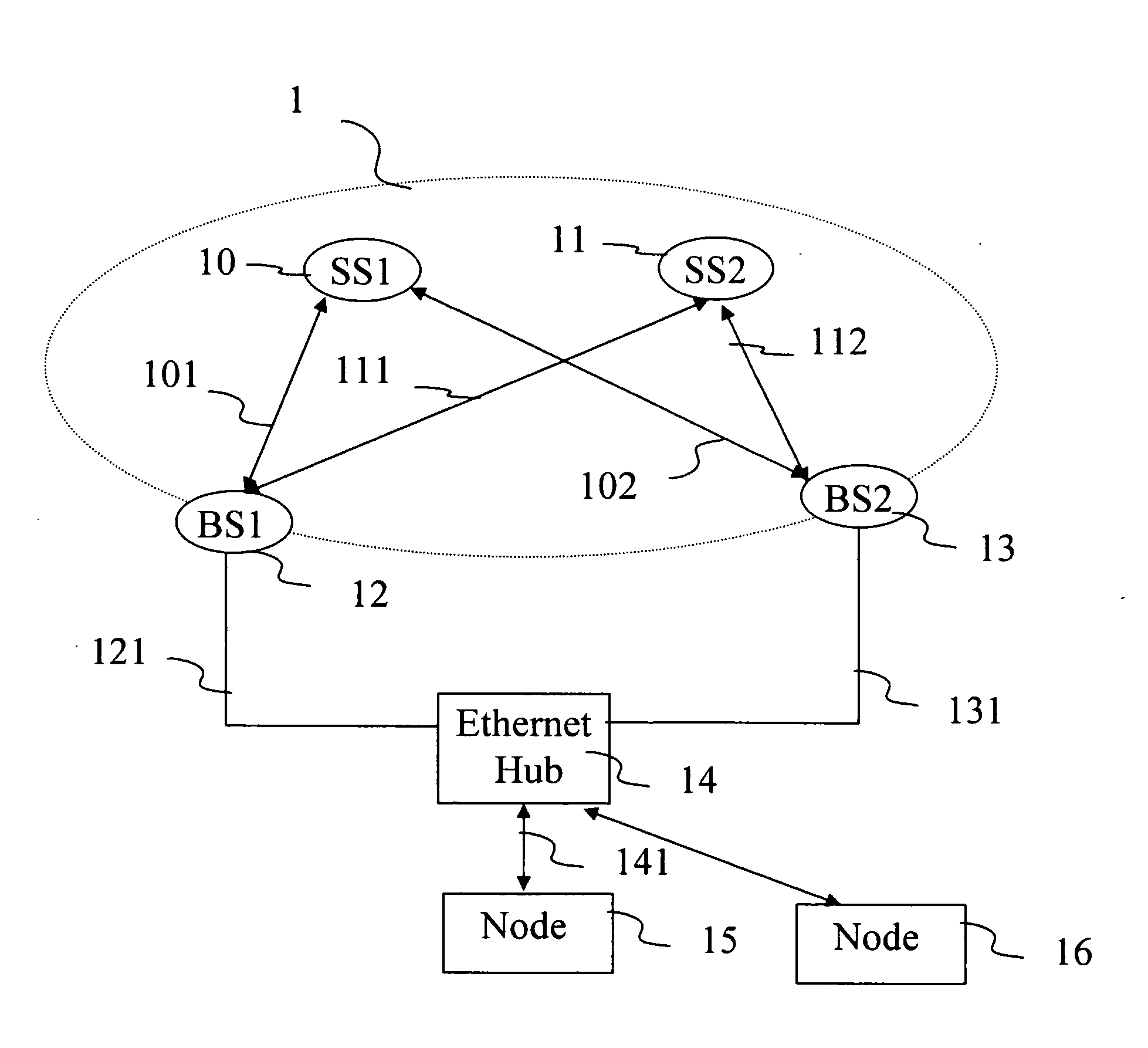
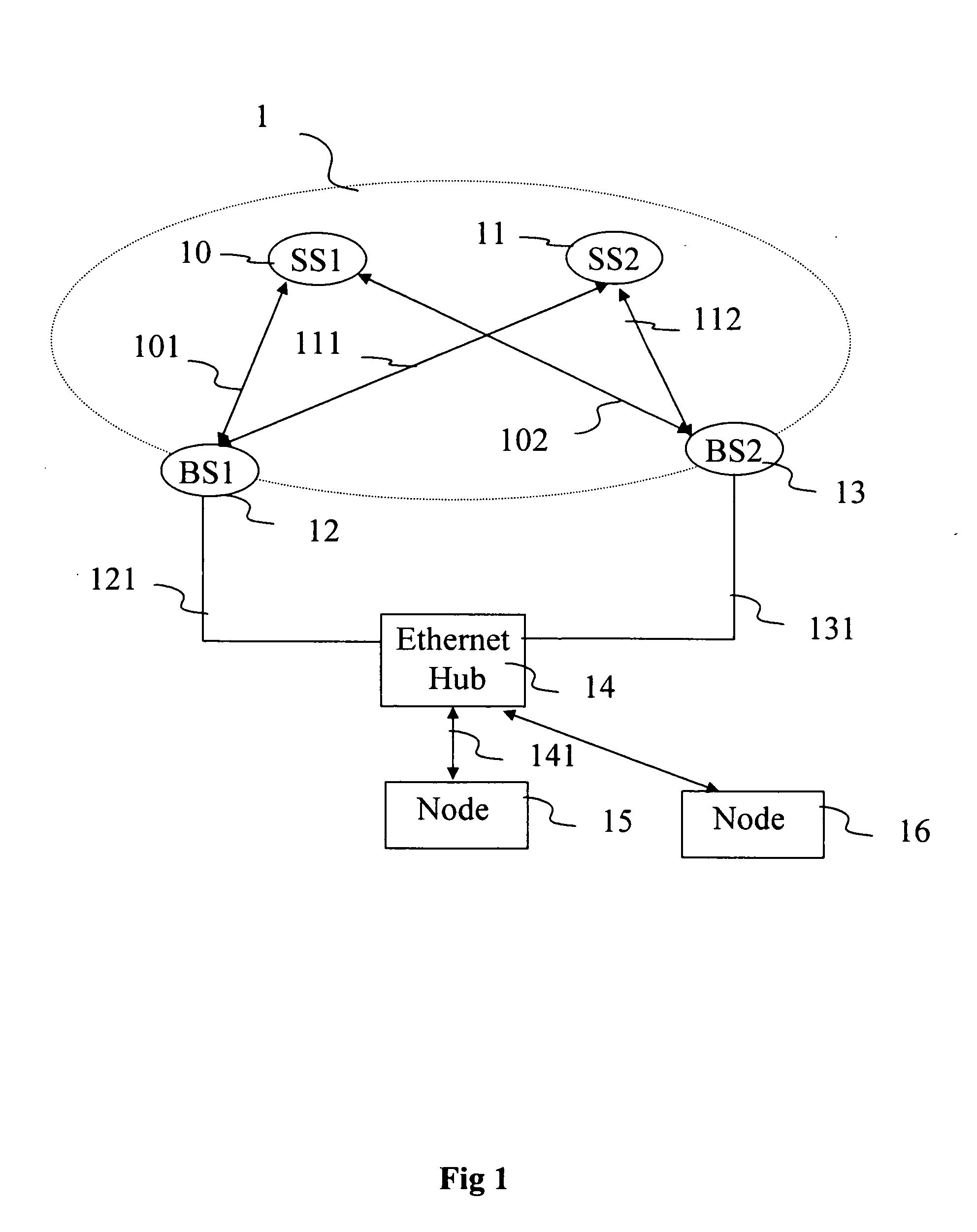
[0027]FIG. 1 shows a communication network comprising a wireless network 1 and a wired Ethernet network.

[0028]The wireless network 1 comprises one or more wireless stations, fixed or, advantageously mobile. The wireless stations are for example two mobile stations (MS) or subscriber stations SS110 and SS211.

[0029]The Ethernet comprises a hub 14 and two nodes 15 and 16 connected to each other by an Ethernet link.

[0030]Stations 10 and 11 can transmit or receive data intended for or coming from the node 15 via relay stations or base stations (BS) BS112 and BS213. The base stations 12 and 13 enable the interface between the wireless network 1 and the Internet network to be provided. Hence, the base station 12 (respectively 13) is connected via a bidirectional wireless link 101 (respectively 102) to the station MS110 and 111 (respectively 112) to the link MS211. The network architecture 1 is such that the network 1 comprises enough base stations to cover the entire zone in which the mobi...


PUM


Abstract

Communication method implementing at least one subscriber station and at least two base stations synchronised and connected to each other by a communication link.In order to prevent breaks in communication, the method comprises a time resource allocation step for the transmission and / or reception of packets by at least one subscriber station, the time resource being specific to each subscriber station and being able to be used with all the base stations.

Description

1. SCOPE OF THE INVENTION[0001]The present invention relates to the wireless telecommunications field and more specifically to the passing of a communication associated with a mobile station from one relay station to another (known as handover).2. TECHNOLOGICAL BACKGROUND[0002]According to the prior art, several wireless network architectures are known. Some of them are based on a centralised architecture. Hence, the Wi-fi system (based on the IEEE 802.11a standard) has a non-centralised architecture with a contention channel access. Such an architecture does not enable Quality of Service (or QoS) to be managed effectively enough for some applications. The Wimax system (based on the IEEE 802.16 standard) has a centralised architecture that allows a more suitable quality of service to be implemented for some applications.[0003]Nevertheless, the techniques implemented in the Wimax networks do not enable a quality of service to be guaranteed for all the applications, for example for vi...

Claims


Application Information

Patent Timeline
IPC IPC(8): H04Q7/00H04W36/02H04W36/08H04W36/26H04W36/38
CPCH04W36/26H04W36/08H04W84/08
Inventor DORE, RENAUDFONTAINE, PATRICKJEANNE, LUDOVIC
Owner INTERDIGITAL CE PATENT HLDG
Learn More