
Microwave applicator with adjustable heating length

a micro-wave applicator and adjustable technology, applied in the field of electromagnetic radiation therapy, can solve the problems of reducing the amount of systemic chemotherapy from reaching the tumor, affecting the treatment effect, so as to achieve the effect of minimizing damage to surrounding normal tissue and better controlling tissue hea

Inactive Publication Date: 2008-09-11
BSD MEDICAL
View PDF61 Cites 33 Cited by
  • Summary
  • Abstract
  • Description
  • Claims
  • Application Information

AI Technical Summary

Benefits of technology

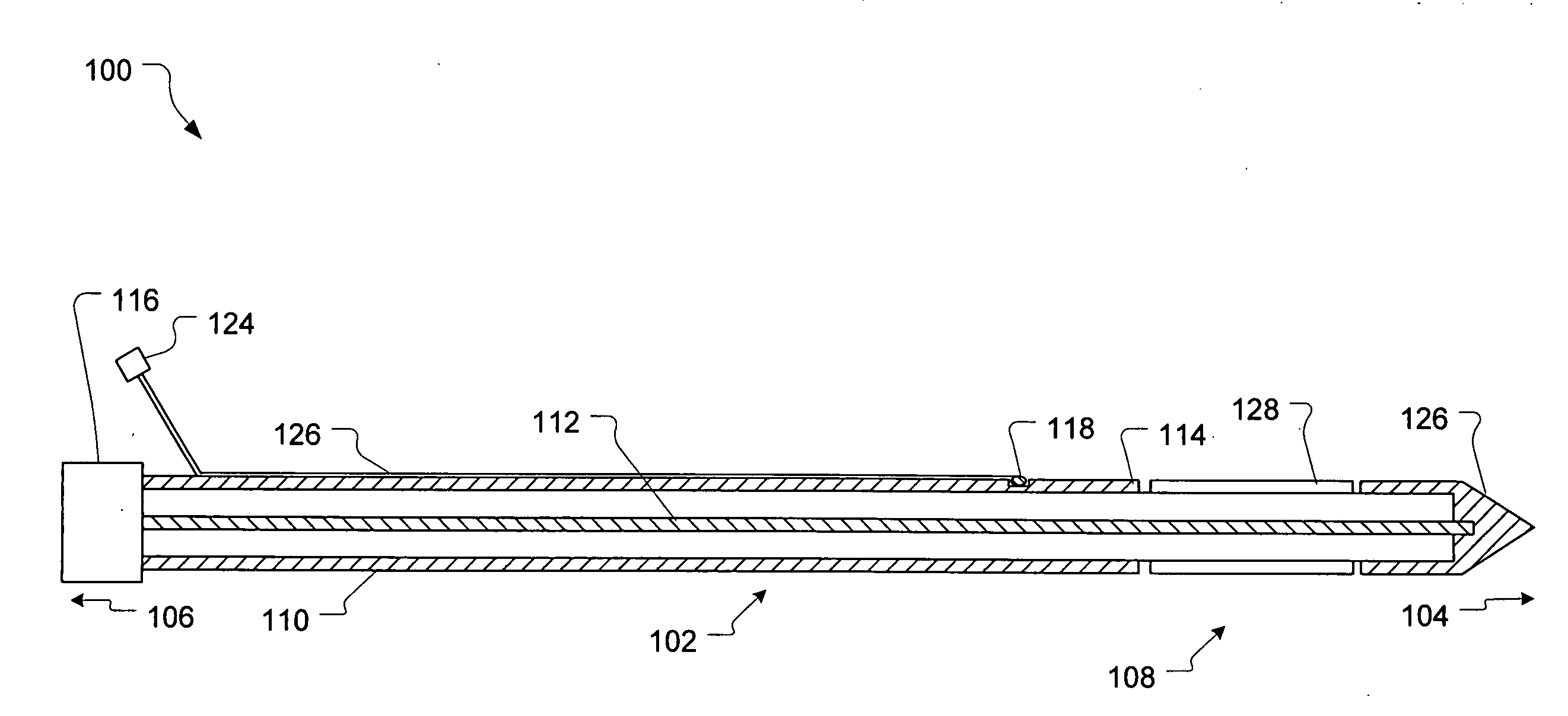
[0012]In one embodiment of the invention, the length of the heating area that is produced during operation of the applicator can be adjusted so the applicator can be adjusted for various sizes of diseased tissue areas to be treated. The length of the heating area is determined by a conductive sleeve around the outside of the applicator positionable along the length of the applicator to expose a selected length of the applicator and antenna. Usually, the conductive sleeve around the outside of the applicator and positionable along the length of the applicator is positionable to expose the proximal end of the applicator and a selected length of the applicator extending from the proximal end toward the distal end of the applicator to thereby control the length of the expected heating area in the living body tissue caused by the antenna during operation of the applicator. This adjustment of the length of the heating area created by the applicator can be used with or without the temperature sensor placement of the invention at the outer margin of the expected heating area.

Problems solved by technology

At temperatures above about 45 degrees C. thermal damage occurs to most normal cells when exposed for more than 30 minutes.
For example, when heating is combined with radiation, it is desirable to maintain the temperature within the diseased tissue within the range of about 42 to 45 degrees C. Higher temperatures are usually undesirable when a combined treatment modality is used because higher temperatures can lead to microvessal collapse causing resistance to radiation therapy and decrease the amount of systemic chemotherapy from reaching the tumor if it has vascular damage.
Lower temperatures are also undesirable because they can fail to provide adequate therapeutic effect.
Therefore, it is important to control the temperature within the desired range for multi-modality treatments and not allow heating of the tissue in the tumor or around the tumor to above 45 degrees C. if such tissue damage from other treatments may be compromised.
At times, in such conditions, the highest tissue temperature may be the limiting factor in heating the tissue.
The outer margin of the overall heat distribution in this tissue volume may then result in damage to normal tissue if such normal tissue is exposed to a thermal dose level that reaches 200 equivalent minutes.
Therefore, for prolonged ablation treatments where the ablation volume is maintained at very high temperatures there is a high risk of damage to surrounding normal tissues.
The process of heating very rapidly to high temperatures that is common in ablation treatments may utilize a rather short exposure time.
However, if such treatments continue for multiple minutes, the blood flow and thermal conduction of the tumor and surrounding tissues will modify the temperature distribution to result in a less predictable heat distribution because the changes occurring in blood flow in such a heated region may not be predictable.
Even when properly placed, however, it has been difficult to ensure that adequate heat is developed in the diseased tissue without overheating surrounding healthy tissue.

Method used


Image

  • Microwave applicator with adjustable heating length
  • Microwave applicator with adjustable heating length
  • Microwave applicator with adjustable heating length

Examples


Embodiment Construction

[0031]Reference will now be made to the exemplary embodiments illustrated in the drawings, and specific language will be used herein to describe the same. It will nevertheless be understood that no limitation of the scope of the invention is thereby intended. Alterations and further modifications of the inventive features illustrated herein, and additional applications of the principles of the inventions as illustrated herein, which would occur to one skilled in the relevant art and having possession of this disclosure, are to be considered within the scope of the invention.

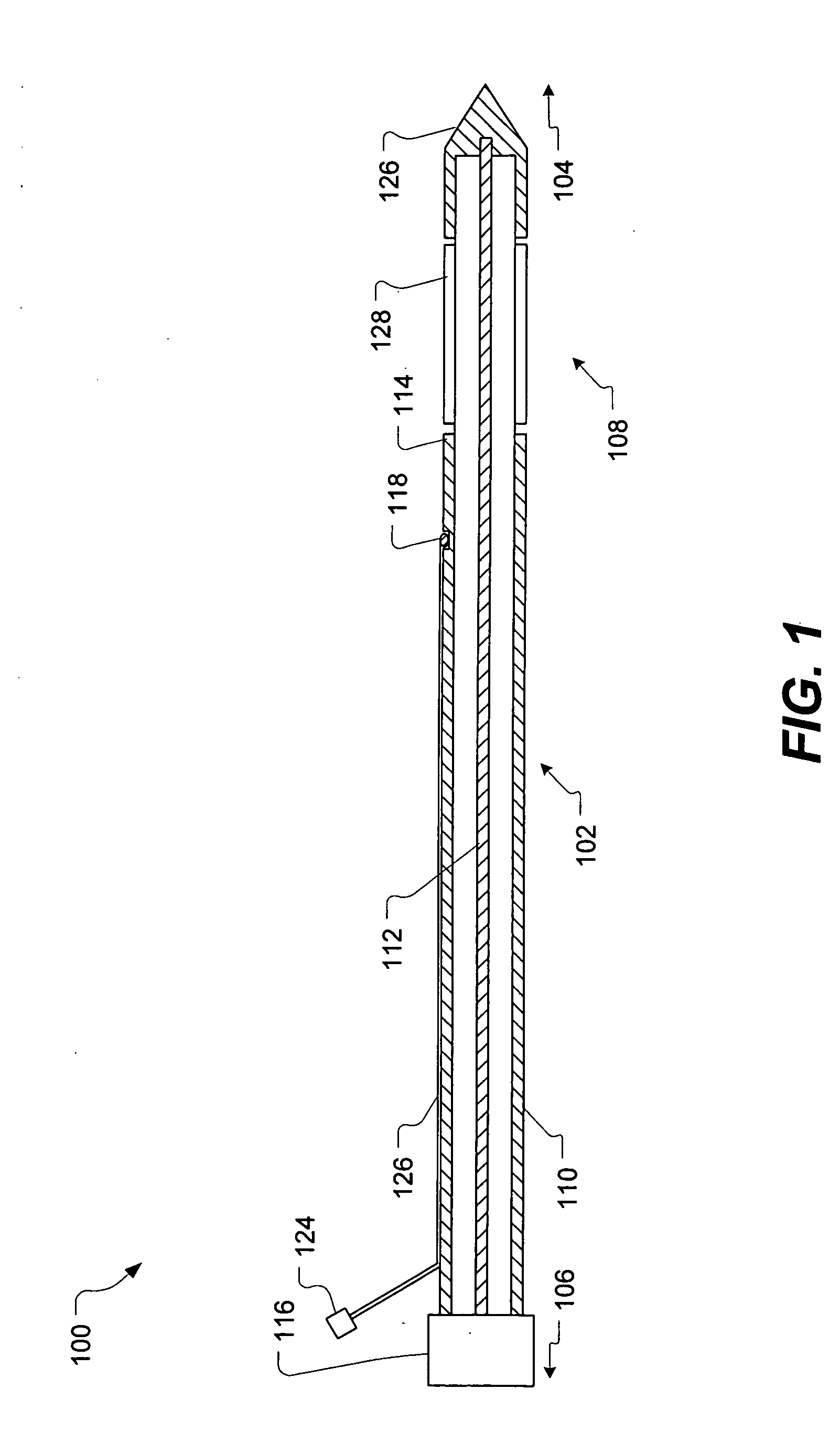
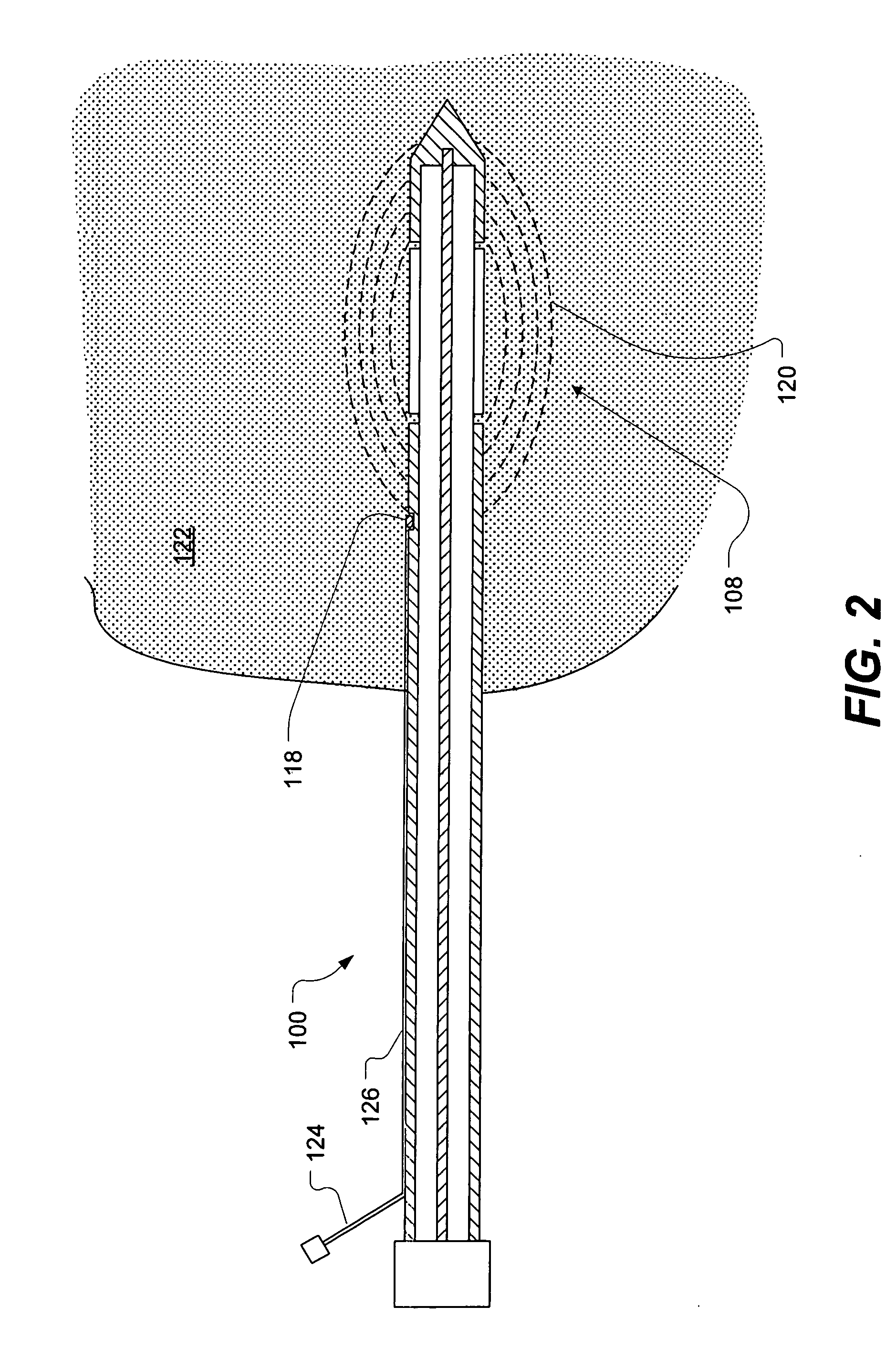
[0032]A microwave applicator for heat treatment of diseased tissue within a living body tissue is illustrated in FIG. 1. The applicator, shown generally at 100, includes an elongate applicator body 102 having a proximal end 104 for insertion into a tissue region of the living body and a distal end 106 for attachment to a source of microwave energy. A means for radiating microwave energy, for example, an antenna 1...


PUM


Abstract

A microwave applicator for applying microwave radiation to body tissue includes a microwave antenna formed by extending the center conductor of a coaxial cable beyond the end of the outer coaxial conductor and providing a conductive outer tip coupled to the center conductor with a space between the end of the outer conductor and the conductive tip. The length of the expected heating area caused by microwave energy applied to the antenna can be adjusted by positioning a conductive sleeve along the length of the antenna from one end of the antenna to cover a portion of the antenna, the length of the heating area being determined substantially by the length of the uncovered portion of the antenna. Treatment can include positioning one or more applicators into body tissue, adjusting the conductive sleeve with respect to the antenna to adjust the length of the heating area for each of the one or more applicators, and applying microwave energy to the applicators.

Description

RELATED APPLICATIONS[0001]This application is a continuation-in-part of copending application Ser. No. 11 / 499,079 filed Aug. 4, 2006, and entitled Microwave Applicator With Margin Temperature Sensing Element.BACKGROUND OF THE INVENTION[0002]1. Field[0003]This invention relates to electromagnetic radiation (EMR) therapy and more particularly to applicators for applying electromagnetic energy to a treatment site to heat the treatment site.[0004]2. State of the Art[0005]The use of electromagnetic (EM) energy to heat tissue for the treatment of disease is known. For example, death, or necrosis, of living tissue cells occurs at temperatures elevated above a normal cell temperature. Above a threshold temperature of about 41.5 degrees C., substantial thermal damage occurs in most malignant cells. At temperatures above about 45 degrees C. thermal damage occurs to most normal cells when exposed for more than 30 minutes. The death rate of heated tissue cells is a function of both the temperat...

Claims


Application Information

Patent Timeline
IPC IPC(8): A61B18/04
CPCA61B18/1206A61B18/1477A61B18/18A61B18/1815A61B2017/00084A61N1/06A61B2018/00791A61B2018/1425A61B2018/1861A61B2019/504A61B2018/00714A61B2034/104
Inventor TURNER, PAUL F.YOUD, THOMAS L.
Owner BSD MEDICAL
Learn More