Current-mode DC-to-DC-converter
a converter and current-mode technology, applied in the field of converters, can solve the problems of signal distortion, slow response to transient loads, low precision,
- Summary
- Abstract
- Description
- Claims
- Application Information
AI Technical Summary
Benefits of technology
Problems solved by technology
Method used
Image

Examples
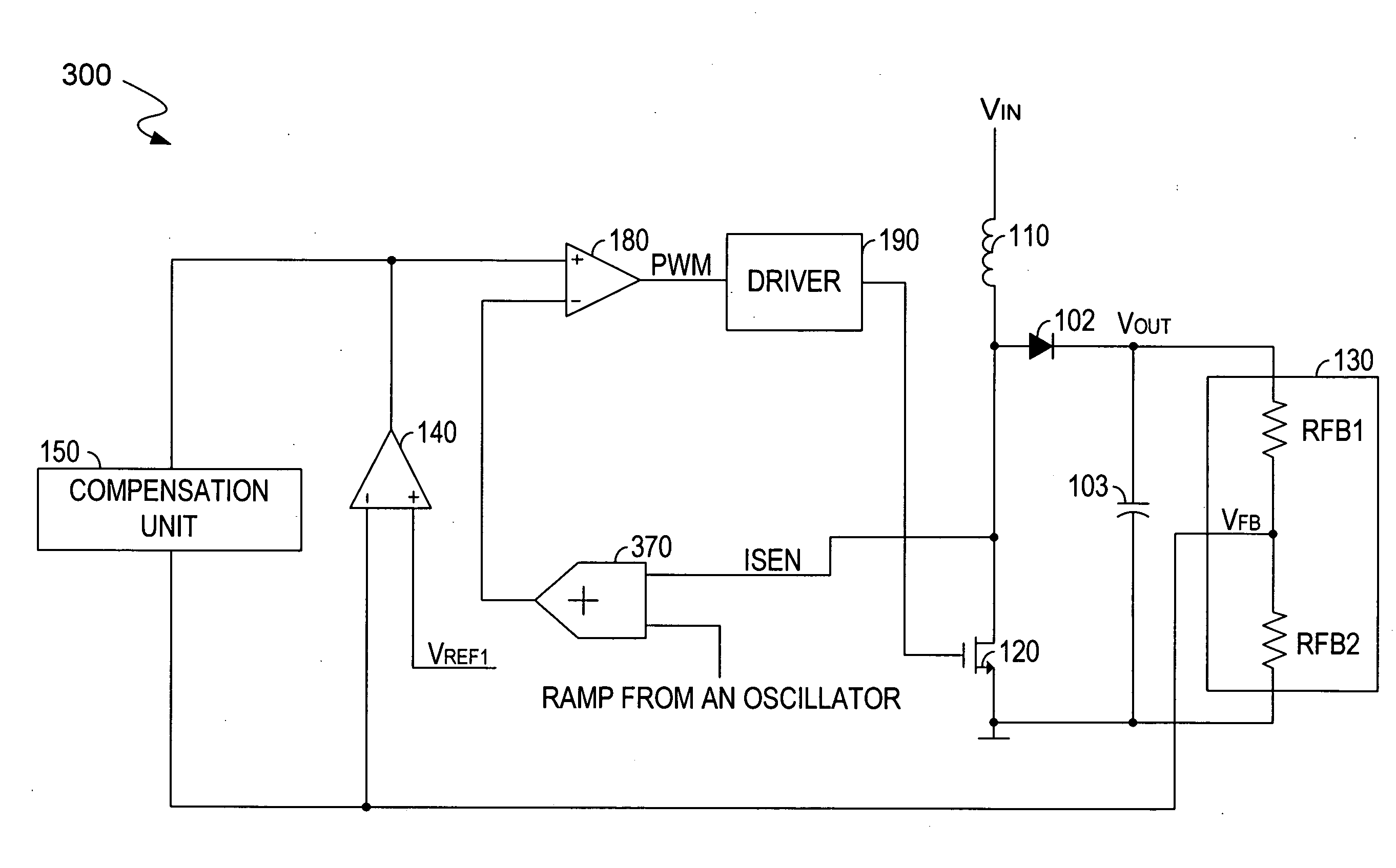
exemplary embodiment 400
[0027]FIG. 4 depicts a schematic diagram of an exemplary embodiment 400 of the current-mode boost converter 300 of FIG. 3. The boost converter 400 includes an oscillator 410 to generate a ramp signal at node 409. A voltage signal ISEN is generated based upon the current flowing through the power switch 120. The adder 370 can add the ramp signal from the oscillator 410 to the voltage signal ISEN and then generate a sum signal at node 419.
[0028]The oscillator 410 includes a current source 401, a capacitor 402, a resistor 403, a discharging switch 404, comparators 405 and 406 and a logic unit 407. The discharging switch 404 is preferably a NMOS transistor. The logic unit 407 generates a pulse signal to control states of the NMOS transistor 404. The pulse signal can control the charging and discharging of the capacitor 402 by controlling the states of the NMOS transistor 404. The current source 401 can provide a current to charge the capacitor 402 when the NMOS transistor 404 is turned ...
exemplary embodiment 700
[0038]FIG. 7 illustrates a simplified schematic diagram of an exemplary embodiment 700 of the current-mode buck converter of FIG. 6. In the buck converter 700, the symbols for the components similar to those in FIG. 3 are consistent. Hence, only the difference will be described in detail for clarity below.
[0039]The buck converter 700 includes an oscillator 710 to generate a ramp signal RAMP at node 709. The oscillator 710 mainly consists of a current sink 701, a capacitor 702, a resistor 703, a discharging switch 704, comparators 705 and 706, and a logic unit 707. The discharging switch 704 can be implemented by a PMOS transistor and is controlled by a pulse signal. The current sink 701 provides a current to pull down the voltage at a lower plate of the capacitor 702 (i.e., node 709) when the discharging switch 704 is turned off. When the discharging switch 704 is turned on, the voltage at node 709 will be pushed to a peak voltage via the resistor 703. The abovementioned process wil...
PUM
 Abstract
Description
Claims
Application Information
 - R&D
- Intellectual Property
- Life Sciences
- Materials
- Tech Scout
- Unparalleled Data Quality
- Higher Quality Content
- 60% Fewer Hallucinations
Browse by: Latest US Patents, China's latest patents, Technical Efficacy Thesaurus, Application Domain, Technology Topic, Popular Technical Reports.
© 2025 PatSnap. All rights reserved.Legal|Privacy policy|Modern Slavery Act Transparency Statement|Sitemap|About US| Contact US: help@patsnap.com