Motion Guide Device

a technology of motion guide and shaft, which is applied in the direction of bearings, shafts and bearings, bearings, etc., can solve the problems of damage to the scoop section at the lower end of the end plate, and achieve the effects of enhancing strength, shortening the scoop section, and increasing the thickness of the scoop section for the balls

Active Publication Date: 2008-09-04
THK CO LTD
View PDF3 Cites 2 Cited by
  • Summary
  • Abstract
  • Description
  • Claims
  • Application Information

AI Technical Summary

Benefits of technology

[0017]According to the invention of claim 1, owing to a larger contact angle, the contact starting position between the ball and the scoop section in scooping the ball can be backed off in the traveling direction of the ball and be placed upward. Thus, the thickness of the scoop section for the balls is increased and the strength is enhanced to allow for coping with high-speed movement. Also, since a front edge of the scoop section can be backed off, the scoop section can be shortened so as to mitigate the damage that would be suffered at the scoop section at high-speed movement. Further, since an upper limit of the contact angle is determined so that the scoop section is placed inside the ball rolling groove, the ball can be scooped even in a deep ball rolling groove.
[0018]As recited in the invention of claim 2, the contact angle is preferably equal to or more than 40° and equal to or less than 60°.
[0019]A scoop angle becomes large with having the contact starting position between the ball and the scoop section backed off in the traveling direction of the ball. According to the invention of claim 3, the formation of the arc surface at the contact starting position can mitigate the scoop angle.
[0020]As the invention recited in claim 4, the scoop section of the present invention is suitable for the end plates of a linear guide.
[0021]According to the invention recited in claim 5, the ball smoothly moves from the Gothic arch groove-shaped scoop section to the circular arc groove-shaped ball escape path (with circular cross section).
[0022]According to the invention recited in claim 6, damages at the scoop section can be mitigated in high-speed movement.

Problems solved by technology

In such a linear guide, it has been that the scoop section at the lower end of the end plate is likely to be damaged when the moving block is attempted to be moved at high speed (e.g., 150 m / min or more).

Method used


Image

  • Motion Guide Device
  • Motion Guide Device
  • Motion Guide Device

Examples


Embodiment Construction

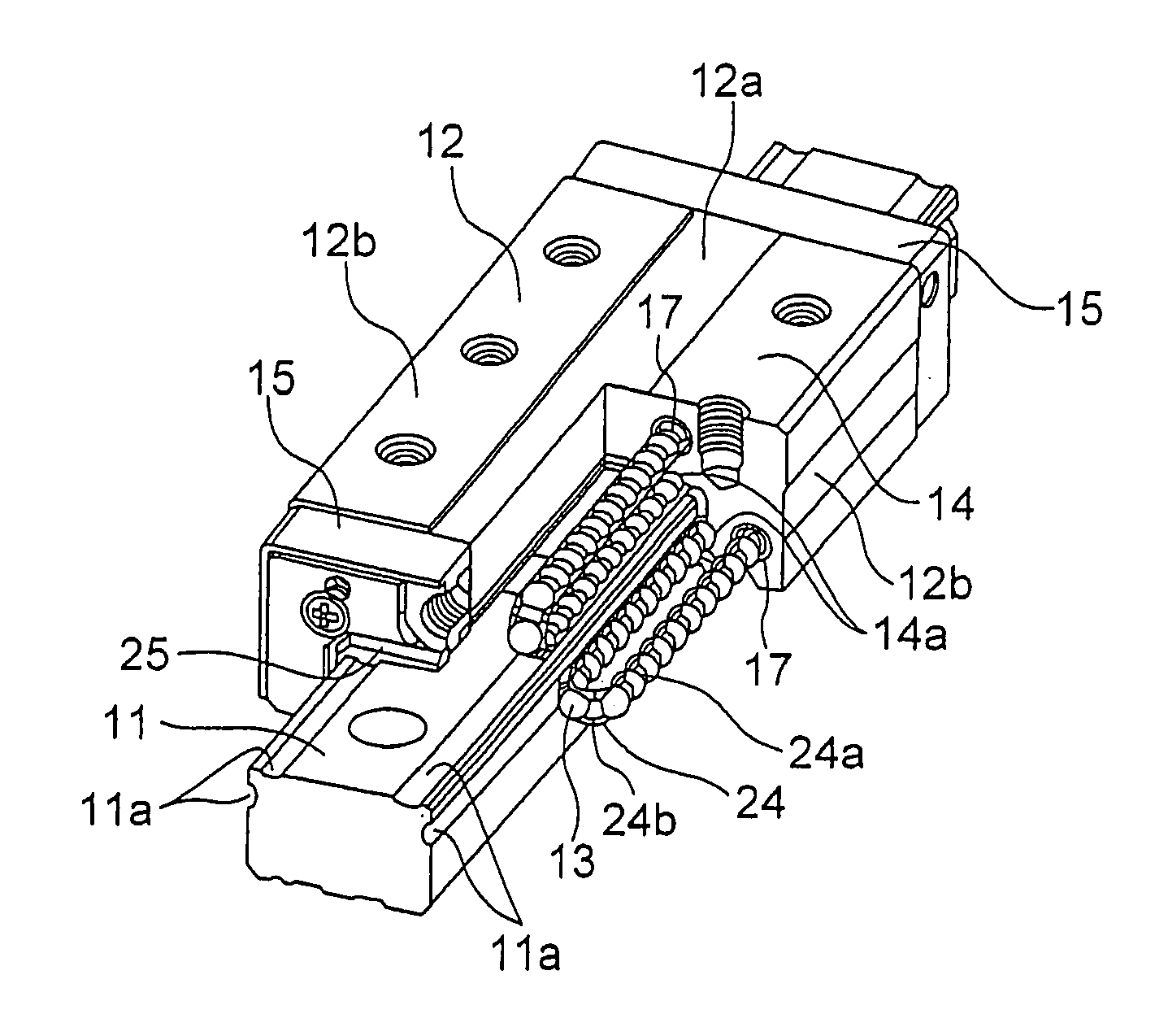
[0053]FIG. 1 illustrates a linear guide as a motion guide device in an embodiment of the present invention. This linear guide is provided with an elongated raceway rail 11 extending linearly and serving a raceway member, and a saddle-shaped moving block 12 serving as a moving member, which is assembled so as to be slidably movable relative to the raceway rail 11. A number of balls 13 capable of rolling movement are intervened between the raceway rail 11 and the moving block 12.

[0054]The raceway rail 11 is formed to have a substantially rectangular cross-section, with a total of four ball rolling grooves 11a being formed in upper portions of left and right side faces and in opposed ends of an upper surface of the raceway rail 11. Each of the ball rolling grooves 11a extends in a longitudinal direction of the raceway rail 11 and formed into a circular arc grooved shape with its cross-section consisting of a single arc.

[0055]The moving block 12 is provided with a central portion 12a be...


PUM


Abstract

A motion guide device having a novel scoop section structure whose scoop section is not likely to break even if a movement member is moved at high speed. A scoop section (22) of a movement block (12) scoops balls (13) that roll in a ball rolling groove (11a) of a raceway rail (11) and introduces them into no-load ball return paths (17, 20). The scoop section (22) is formed in a Gothic arch groove shape in which the scoop section (22) is in two-point contact with a ball (13). In a cross-section orthogonal to the advance direction of the balls (13), an angle (contact angle α) formed by a line L1 that connects a point P at which the scoop section (22) and a ball (13) are in contact and the center C of the ball (13) and a line L2 that connects the center of the ball (13) and a bottom (22a) of the Gothic arch groove-shaped scoop section (22) exceeds 30 degrees and is not more than an angle γ formed by a line L3 that connects the center C of the ball (13) rolling in the ball rolling groove (11a) of the raceway rail (11) and an edge (35) of the ball rolling groove (11a) of the raceway rail (11) and the line L2 that connects the center C of the ball (13) and the bottom of the ball rolling groove (11a).

Description

TECHNICAL FIELD[0001]The present invention relates to a motion guide device, such as a linear guide or a ball spline in which a moving member moves relative to a raceway member. Particularly, the present invention relates to a motion guide device in which a ball that rolls in a ball rolling groove of a raceway member is scooped by a scoop section of a moving member so as to be introduced into a no-load ball return path.BACKGROUND ART[0002]A linear guide, one type of a motion guide device, is provided with a raceway rail in which a plurality of ball rolling grooves are formed, extending parallel to each other, and a saddle-shaped moving block which is assembled so as to be slidably movable along the raceway rail through a number of rolling bodies, such as balls. The moving block is formed with a plurality of load ball rolling grooves opposed to the ball rolling grooves in the raceway rail, and no-load ball return paths each of which connects one end of the load ball rolling groove an...

Claims


Application Information

Patent Timeline
Patent Type & Authority Applications(United States)
IPC IPC(8): F16C29/06
CPCF16C29/0642F16C29/0609F16C29/06
Inventor MICHIOKA, HIDEKAZUMOCHIZUKI, HIROAKISAKUYAMA, TAKASHI
Owner THK CO LTD
Why Eureka
Try Eureka