Brake system for hybrid electric vehicle and control method thereof

a hybrid electric vehicle and brake system technology, applied in the direction of braking system, vehicle position/course/altitude control, instruments, etc., can solve the problems of increased development time and cost of the pedal simulator, and inability to obtain the desired braking for

Inactive Publication Date: 2008-09-04
HYUNDAI MOTOR CO LTD
View PDF15 Cites 34 Cited by
  • Summary
  • Abstract
  • Description
  • Claims
  • Application Information

AI Technical Summary

Benefits of technology

[0020]Preferably, the hydraulic brake adjuster further includes a first solenoid valve, a second solenoid valve, a third solenoid valve and a fourth solenoid valve. The control unit opens only the first solenoid valve and the third solenoid valve to form a second hydraulic line between the reservoir and the wheel cylinders and operates the hydraulic pump to provide hydraulic braking pressure to wheel cylinders. The control unit opens only the second solenoid valve and the third solenoid valve to form a third hydraulic line so as to decrease hydraulic pressures of the wheel cylinders by draining back the brake oil to the reservoir.
[0023]Furthermore, the booster negative pressure supplying unit includes a vacuum tank having a predetermined volume to prevent the negative pressure in the booster from being rapidly reduced during driver's repeated braking.
[0025]Preferably, the control method of the present invention further comprises the step of driving a hydraulic pump of the hydraulic brake adjuster to supply brake oil from a reservoir to the wheel cylinders, thus increasing the hydraulic braking torque, if the maximum regenerative braking torque is so reduced that the total braking torque of hydraulic braking torque and maximum regenerative braking torque goes below the target braking torque.
[0026]Suitably, the control method of the present invention further comprises the step of stopping the hydraulic pump of the hydraulic brake adjuster to return the brake oil from the wheel cylinders to the reservoir, thus reducing the hydraulic braking torque, if the maximum regenerative braking torque is so increased that the total braking torque of hydraulic braking torque and maximum regenerative braking torque goes beyond the target braking torque.

Problems solved by technology

However, an effort of the brake pedal pressed by a driver is not transmitted to respective wheel cylinder hydraulic pressures, and a brake hydraulic pressure is generated by an electrical operation of the EHB system.
Accordingly, the EHB system has a problem in that it may cause an electric malfunction at any time and thereby a desired braking force cannot be obtained during such an electric malfunction.
Moreover, the EHB system has another problem in that a separate pedal simulator is required to obtain the same pedal feel as the existing hydraulic braking system through the EHB system, and thereby development time and cost for the pedal simulator are increased.

Method used


Image

  • Brake system for hybrid electric vehicle and control method thereof
  • Brake system for hybrid electric vehicle and control method thereof
  • Brake system for hybrid electric vehicle and control method thereof

Examples


Embodiment Construction

[0037]Reference will now be made in detail to various embodiments of the present inventions, examples of which are illustrated in the accompanying drawings and described below. While the inventions will be described in conjunction with exemplary embodiments, it will be understood that present description is not intended to limit the inventions to those exemplary embodiments. On the contrary, the inventions are intended to cover not only the exemplary embodiments, but also various alternatives, modifications, equivalents and other embodiments, which may be included within the spirit and scope of the invention as defined by the appended claims.

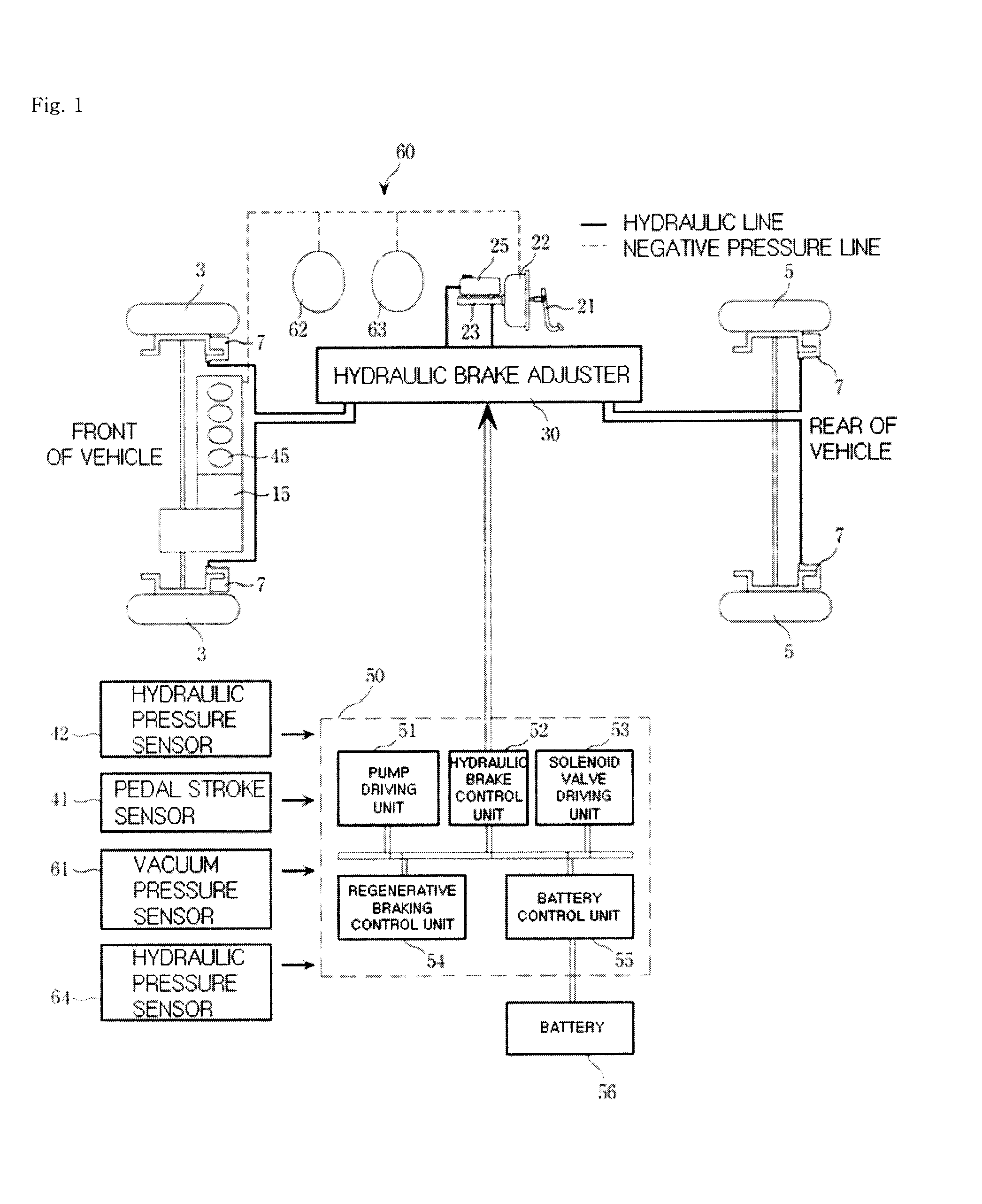
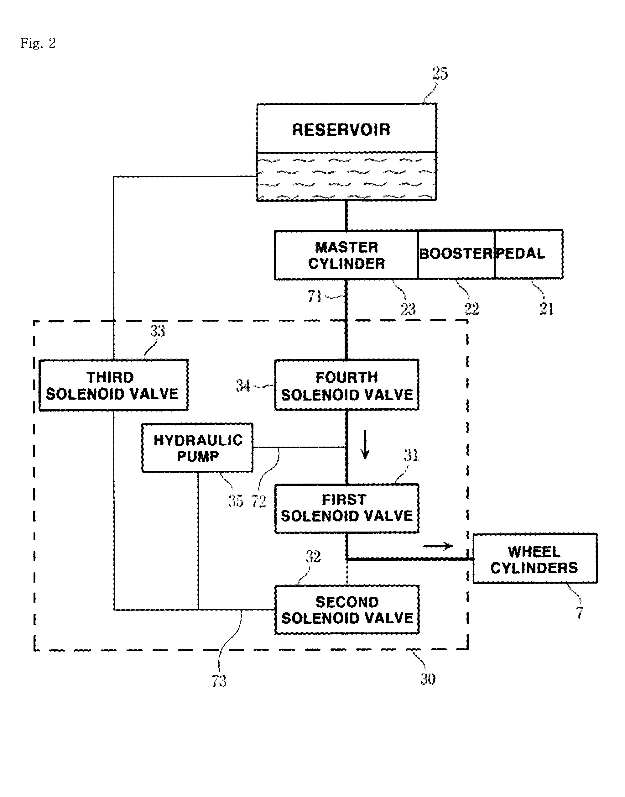
[0038]FIG. 1 is a schematic diagram showing a brake system for a hybrid electric vehicle in accordance with the present invention. The brake system for a hybrid electric vehicle of the present invention broadly comprises a regenerative braking system generating a regenerative braking force, a hydraulic braking system providing a hydraulic brakin...


PUM


Abstract

The present invention provides a brake system and its control method for a hybrid electric vehicle, comprising a driving motor generating a regenerative braking torque; a hydraulic pressure supplying unit including a brake pedal, a booster and a master cylinder, a first hydraulic line, and a reservoir; a hydraulic brake adjuster for controlling a hydraulic braking pressure; a target braking force detection unit, including a pedal stroke sensor and a hydraulic pressure sensor, for detecting a target braking torque of a driver; and a control unit controlling the driving motor by calculating a maximum regenerative braking torque based on a rotational speed of the driving motor, etc. and controlling the hydraulic brake adjuster to change a hydraulic braking torque to meet the target braking torque in accordance with the thus calculated maximum regenerative braking torque by compensating an braking torque with the hydraulic braking torque.

Description

CROSS-REFERENCE TO RELATED APPLICATION[0001]This application claims under 35 U.S.C. §119(a) on Korean Patent Application No. 10-2006-0072604 filed on Aug. 1, 2006, the entire contents of which are incorporated herein by reference.BACKGROUND OF THE INVENTION[0002](a) Field of the Invention[0003]The present invention relates to a brake system for a hybrid electric vehicle and a control method thereof and more particularly to a brake system and a control method of incorporating a hydraulic braking system used in gasoline and diesel vehicles into a regenerative braking system, thus obtaining the target braking torque through a cooperative control of the regenerative braking system and the hydraulic braking system.[0004](b) Background Art[0005]A hybrid electric vehicle is a next generation environment-friendly vehicle in which a combustion engine and a driving motor driven by electrical energy stored in a battery are simultaneously assembled.[0006]When stopping the driving motor in such ...

Claims


Application Information

Patent Timeline
IPC IPC(8): F16D55/224G06F19/00B60K6/48B60L7/24B60T8/17B60T17/00B60W10/08B60W10/18B60W20/00
CPCB60L7/26B60T2270/604B60T8/4072B60T8/267B60L7/10
Inventor JEON, GAB BAE
Owner HYUNDAI MOTOR CO LTD
Why Eureka
Try Eureka