
Electrical connecting apparatus

a technology of connecting apparatus and tips, which is applied in the direction of temperature compensation modification, measurement devices, instruments, etc., can solve the problems of misregistration, greater such thermal expansion and misregistration of tips, and achieve the effect of preventing the displacement of probes

Inactive Publication Date: 2008-08-21
NIHON MICRONICS
View PDF5 Cites 16 Cited by
  • Summary
  • Abstract
  • Description
  • Claims
  • Application Information

AI Technical Summary

Benefits of technology

[0019]Thus, even if the device under test is heated or cooled, the probe board is cooled or heated by the moving air, and the thermal expansion rate of the probe board is greater than that of the device under test by from 1 ppm / ° C. to 2 ppm / ° C., so that misregistration of the tip of the contact relative to the connection terminal of the device under test is restrained, thereby preventing the tip of the contact from detaching from the connection terminal of the device under test to enable an accurate test.

Problems solved by technology

In a conventional electrical connecting apparatus, however, by changing the temperature of a device under test, for example, when the temperature of the device under test is raised, the temperature of the electrical connecting apparatus rises due to heat from a device under test, which causes thermal expansion in the apparatus.
As a result, an arrangement pitch of contacts is changed greatly, thereby creating a so-called misregistration (i.e., displacement) wherein tips are shifted relative to the contact terminals of the device under test.
The larger the electrical connecting apparatus becomes, the greater such thermal expansion and misregistration of the tips become.
As mentioned above, when the amount of displacement of the tips to the connection terminals of the device under test becomes larger, there appear cases where the tips do not contact the connection terminals of the device under test, thereby disabling an accurate test.

Method used


Image

  • Electrical connecting apparatus
  • Electrical connecting apparatus
  • Electrical connecting apparatus

Examples


embodiment

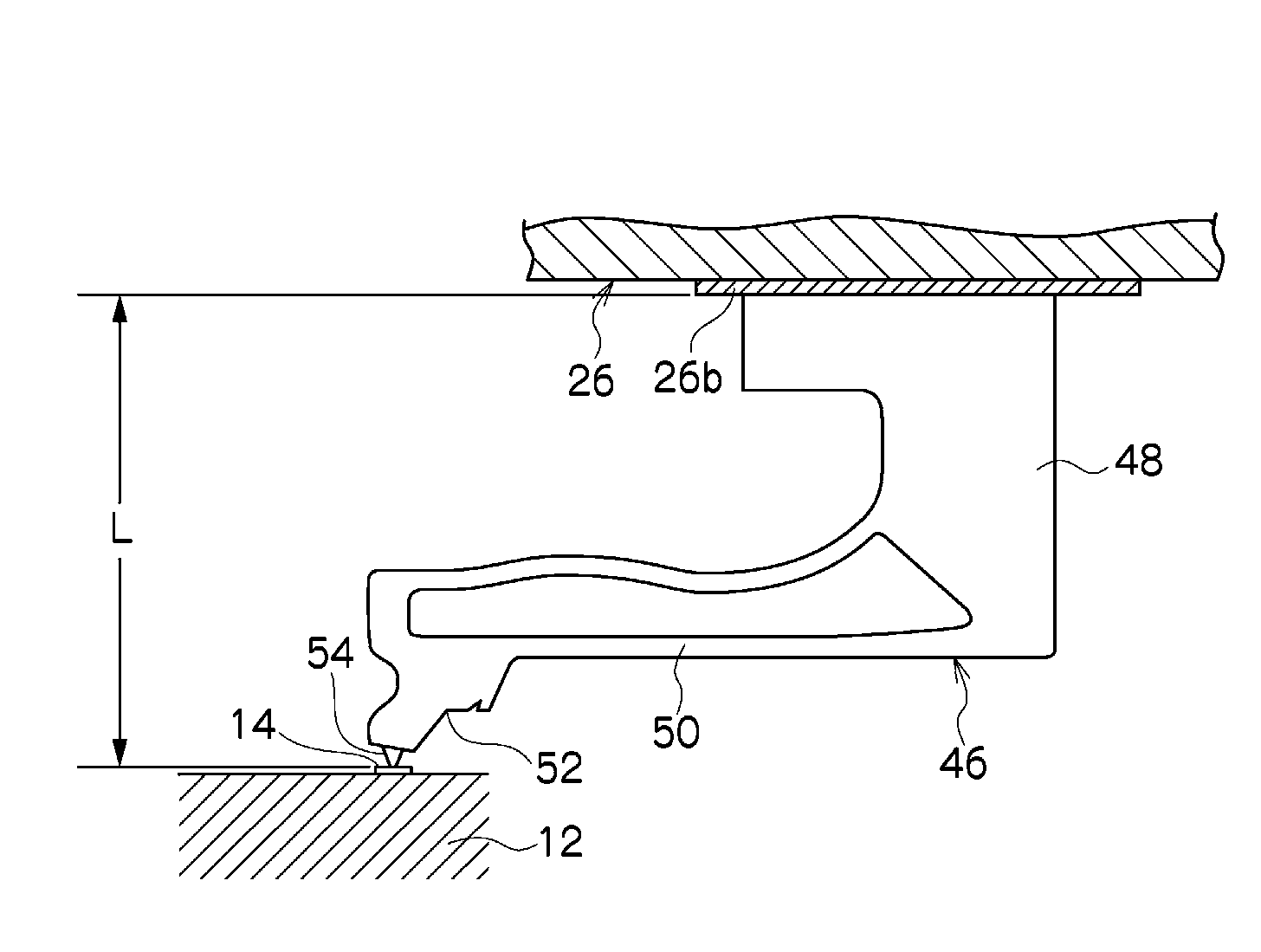
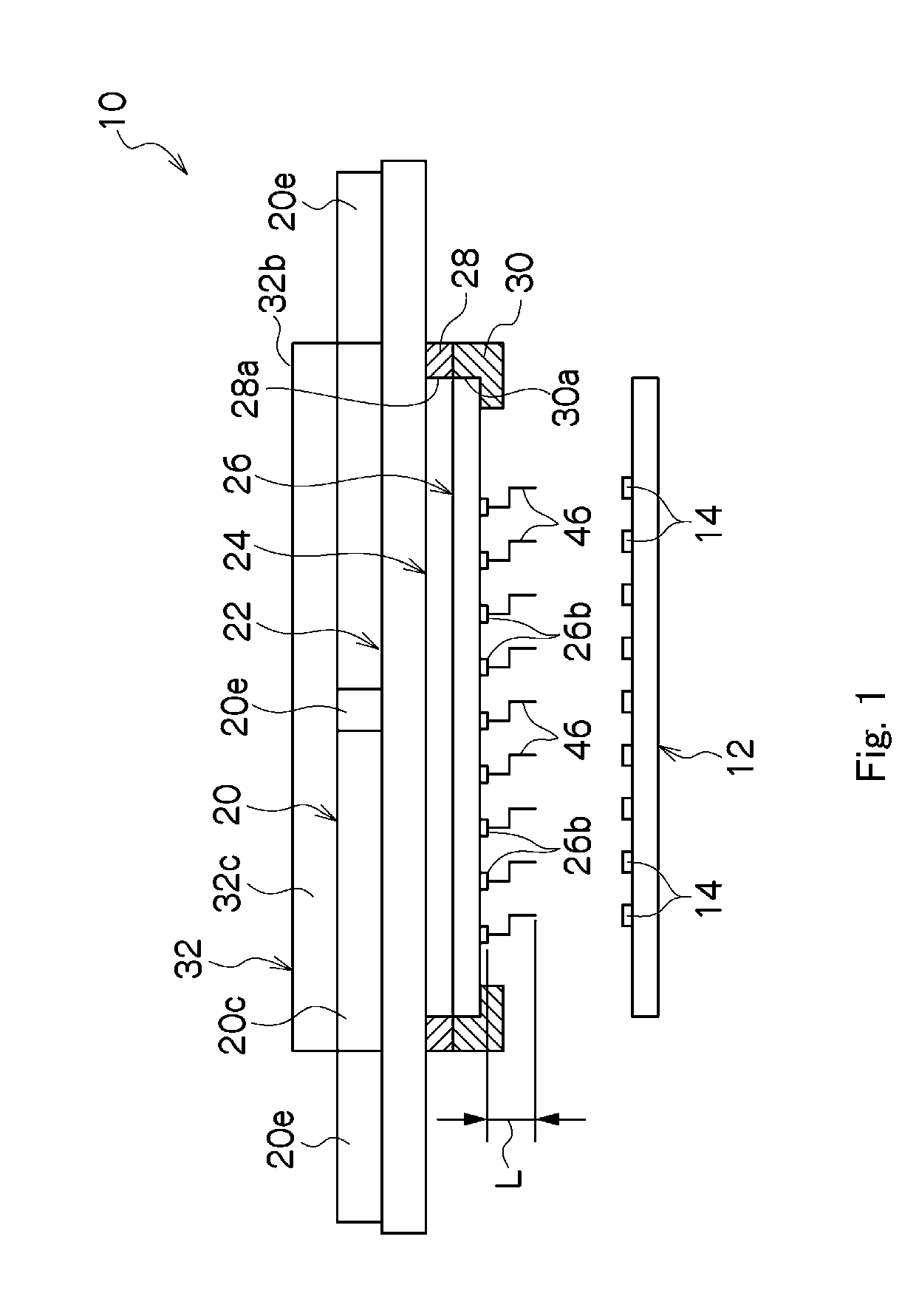
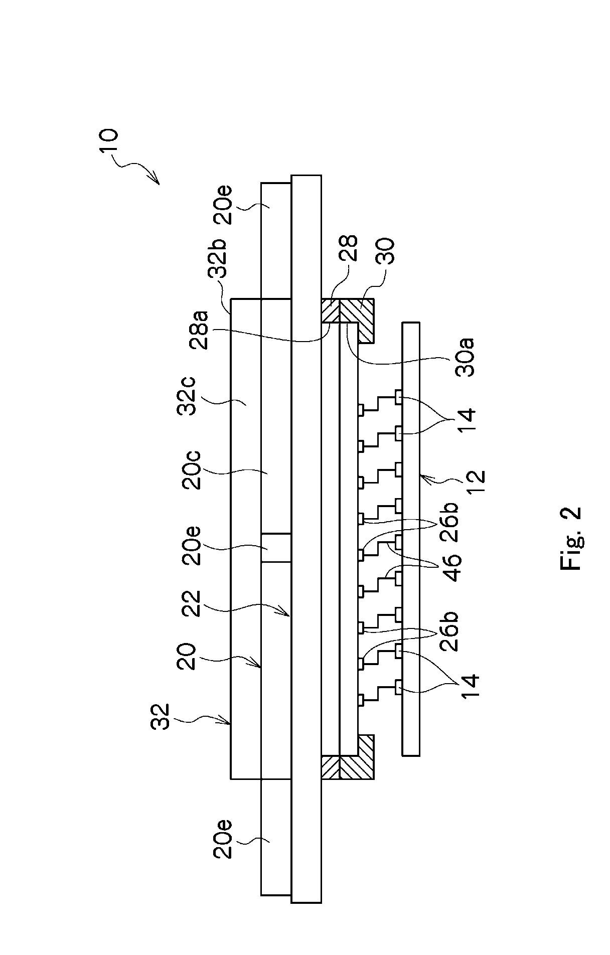
[0050]Referring to FIGS. 1 through 3, the electrical connecting apparatus 10 is disposed in a tester (not shown) for testing an integrated circuit as a device under test 12. The device under test 12 may be at least one integrated circuit cut from a wafer, or at least one integrated circuit within an uncut wafer. In either case, the device under test 12 has a plurality of electrical connection terminals 14 such as electrode pads on the upside.

[0051]As shown in FIG. 1, the connecting apparatus 10 comprises: a flat plate-like support member 20 as viewed from the front side; a circular flat plate-like wiring board 22 held on the underside of the support member 20; a flat plate-like electrical connector 24 disposed on the underside of the wiring board 22; a flat plate-like probe board 26 disposed on the underside of the electrical connector 24; a base ring 28 in which a rectangular or circular central opening 28a for receiving the electrical connector 24 is formed; and a fixed ring 30 fo...


PUM


Abstract

To restrain misregistration of tips due to change in temperature, an electrical connecting apparatus is used for connection of a tester, and electrical connection terminals of a device under test to undergo electrical test by the tester. The electrical connecting apparatus comprises a probe board having a plurality of probe lands on its underside; and a plurality of contacts having tip portions to be brought into contact with a base end portion fixed at the respective probe lands and the connection terminals of the device under test. The measure from the tip of each contact and the probe land ranges from 1.1 to 1.3 mm, and the coefficient of thermal expansion of the probe board is greater than the coefficient of thermal expansion of the device under test within the range from 1 to 2 ppm / ° C.

Description

TECHNICAL FIELD[0001]The present invention relates to an electrical connecting apparatus for connecting a tester and an electrical connection terminal of a device under test to undergo an electrical test by the tester.BACKGROUND[0002]An electrical performance test, (i.e., inspection or measurement test) of a device under test such as a semiconductor integrated circuit is conducted by use of an electrical connecting apparatus such as a probe card provided in a tester.[0003]There is an electrical connecting apparatus of this type in which a plurality of contacts (i.e., probes) to be brought into contact with a connection terminal (i.e., electrode) of the device under test are disposed on the underside of a probe board, a wiring board is disposed above the probe board, an electrical connector (i.e., socket device) is disposed between the probe board and the wiring board to connect a wiring circuit provided on the wiring board and a wiring circuit provided on the probe board (Patent Doc...

Claims


Application Information

Patent Timeline
IPC IPC(8): G01R1/067
CPCG01R1/44G01R1/07342G01R1/06
Inventor MIYAGI, YUJISATO, HITOSHIMIURA, KIYOTOSHI
Owner NIHON MICRONICS
Learn More