Eureka AIR delivers breakthrough ideas for toughest innovation challenges, trusted by R&D personnel around the world.

Coiled tubing clamping device and injection head using same

A technology of clamping mechanism and oil pipe, which is applied in the direction of drill pipe, casing, earthwork drilling, etc. It can solve the problems that the clamping block cannot slide, reduce the service life of the oil pipe, wear the oil pipe, etc., so as to avoid injury or wear and prolong the use Life and reliability improvement effects

Active Publication Date: 2014-05-07
YANTAI JEREH OILFIELD SERVICES GROUP +1
View PDF9 Cites 112 Cited by
  • Summary
  • Abstract
  • Description
  • Claims
  • Application Information

AI Technical Summary

Problems solved by technology

The clamping mechanism with rolling bodies used on the commonly used injection head has the following defects due to the connection structure between the clamping block and the clamping block seat: one is that the clamping block used on the clamping mechanism cannot be clamped Sliding on the holding block seat is not conducive to the active centering adjustment of the clamping block, resulting in wear of the oil pipe and reducing the service life of the oil pipe; the second is the traditional clamping mechanism, the direct contact between the clamping block and the holding block seat is not conducive to Buffer the impact of the clamping block on the oil pipe, causing serious wear to the oil pipe
Although this has better solved the above-mentioned problems caused by the inability of the clamping block to move, and made it easier to replace the clamping block, it still has the following disadvantages: due to the random movement of the clamping block in the work, the limit bolts are affected. Frequent shear force causes the limit bolt to break frequently, which affects the continuous operation of the injection head; when replacing the clamping block, it is necessary to move the clamping block along the direction of the oil pipe to unhook the hook block and the boss, which is inconvenient to operate

Method used


Image

  • Coiled tubing clamping device and injection head using same
  • Coiled tubing clamping device and injection head using same
  • Coiled tubing clamping device and injection head using same

Examples


Embodiment Construction

[0032] The specific embodiment of the present invention is described in detail below in conjunction with accompanying drawing:

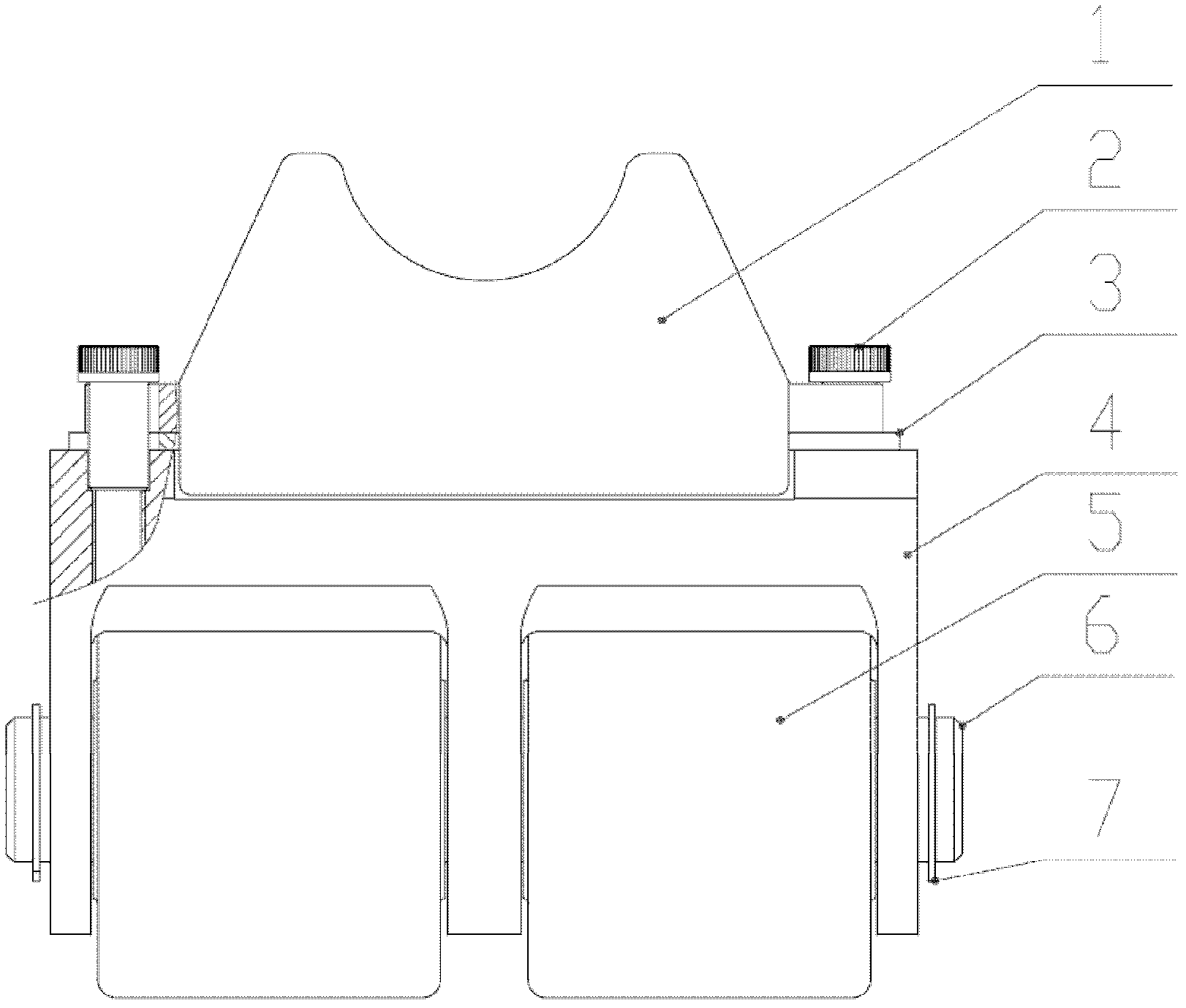
[0033] Such as Figure 1-Figure 7 As shown: a coiled tubing clamping mechanism, including a saddle-shaped clamping block 1 and a clamping block seat 4, the clamping block seat 4 includes a pin shaft 6 and a rolling body 5 sleeved on the pin shaft, the The clamping block seat 4 is provided with two through holes 402 for inserting and connecting the pin shaft with the injection head chain along the direction of the pin shaft 6, and the upper part of the clamping block seat 4 is provided with three partitions 403. The partition 403 is provided with a pin hole 401 for installing the pin 6;

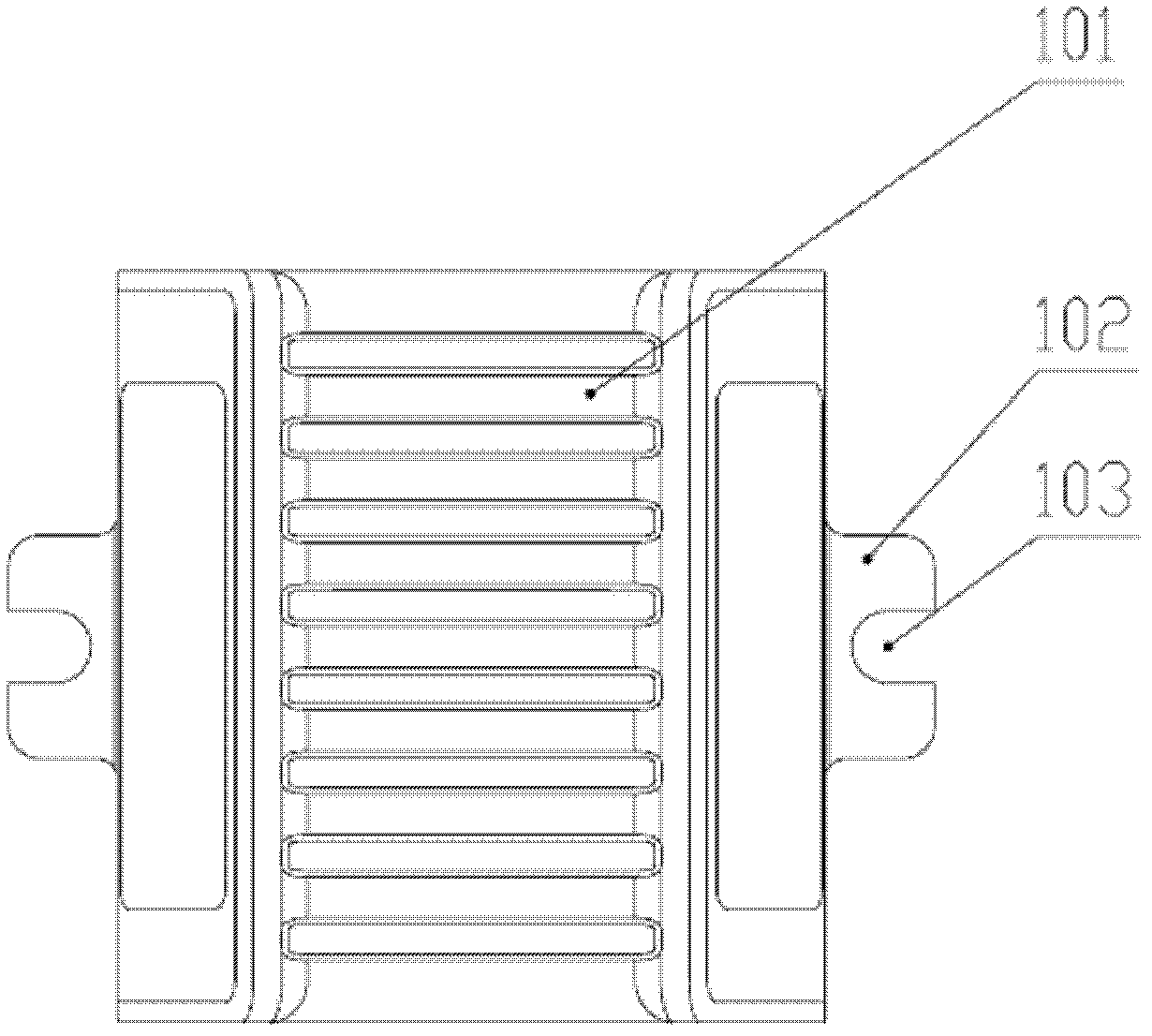
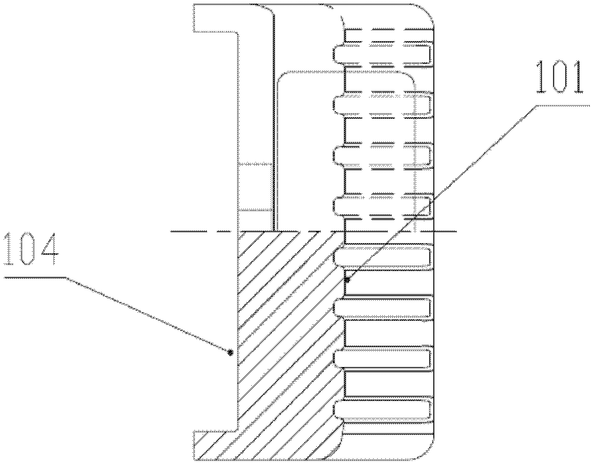
[0034] Both sides of the saddle-shaped clamping block 1 are provided with a tongue table 102, the tongue table 102 is provided with an opening 103, the back of the saddle-shaped clamping block 1 is provided with a groove 104, and the clamping block A pair of bosses...


PUM


Abstract

A coiled tubing clamping mechanism comprises a saddle-shaped clamping block (1) and a clamping block seat (4). The saddle-shaped clamping block (1) is connected to the clamping block seat (4). Two sides of the saddle-shaped clamping block (1) are provided with a tongue platform (102). The tongue platform (102) is provided with an open hole (103). The back of the saddle-shaped clamping block (1) is provided with a groove (104). Two sides of the clamping block seat (4) are provided with a pair of bosses (406) respectively. The groove (104) of the saddle-shaped clamping block (1) is inserted in a holding slot (405) formed by the bosses (406) of the clamping block seat. A traverse gap is kept between the groove (104) and the holding slot (405). The clamping block seat (4) is provided with a positioning screw (2) for limiting the position of the saddle-shaped clamping block (1). Also disclosed is an injector head using the coiled tubing clamping mechanism, comprising a tubing clamping mechanism (11) and a drive chain (13). The tubing clamping mechanism (11) is mounted on the drive chain (13) through two pin holes (401) in the clamping block seat (4). The present invention can effectively prevent the tubing from being worn, is reliable in use, and makes it convenient to replace the clamping block.

Description

technical field [0001] The invention relates to the field of oil drilling and production equipment, in particular to a clamping mechanism for a coiled tubing, and an injection head using the clamping mechanism. Background technique [0002] The injection head is the core component of the coiled tubing equipment, and the clamping mechanism provides the clamping force for the injection head to transport the coiled tubing. The clamping mechanism with rolling bodies used on the commonly used injection head has the following defects due to the connection structure between the clamping block and the clamping block seat: one is that the clamping block used on the clamping mechanism cannot be clamped Sliding on the holding block seat is not conducive to the active centering adjustment of the clamping block, resulting in wear of the oil pipe and reducing the service life of the oil pipe; the second is the traditional clamping mechanism, the direct contact between the clamping block a...

Claims


Application Information

Patent Timeline
Patent Type & Authority Patents(China)
IPC IPC(8): E21B19/22
CPCE21B19/22
Inventor 刘东方基垒于清峰
Owner YANTAI JEREH OILFIELD SERVICES GROUP
Why Eureka
Eureka Blog
Learn More