
Tunneling magnetic sensing element having free magnetic layer inserted with nonmagnetic metal layers

a magnetic sensing element and free magnetic layer technology, applied in the field of magnetic sensing elements, can solve the problem of easy cause of barkhausen noise, and achieve the effect of increasing the rate of change resistance (r/r), and effectively increasing the rate of change resistan

Inactive Publication Date: 2008-08-07
ALPS ALPINE CO LTD
View PDF6 Cites 7 Cited by
  • Summary
  • Abstract
  • Description
  • Claims
  • Application Information

AI Technical Summary

Benefits of technology

[0010]The present invention provides a tunneling magnetic sensing element in which the rate of change in resistance (ΔR / R) can be increased.
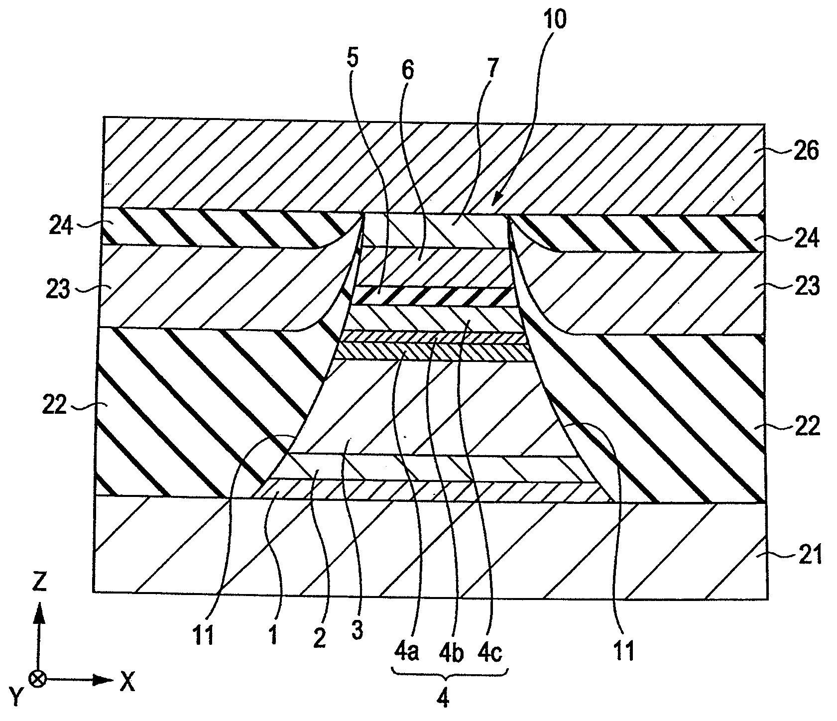
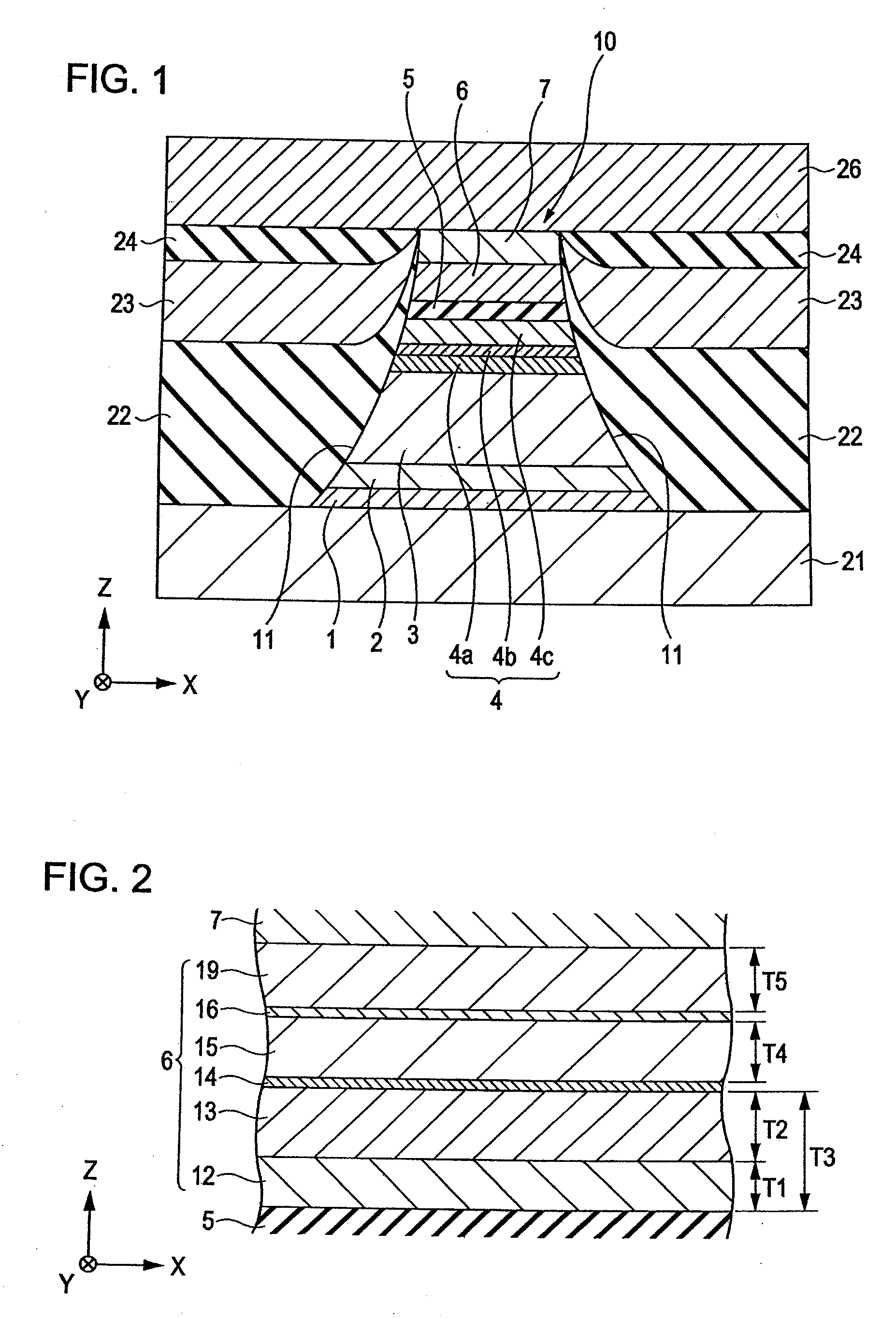
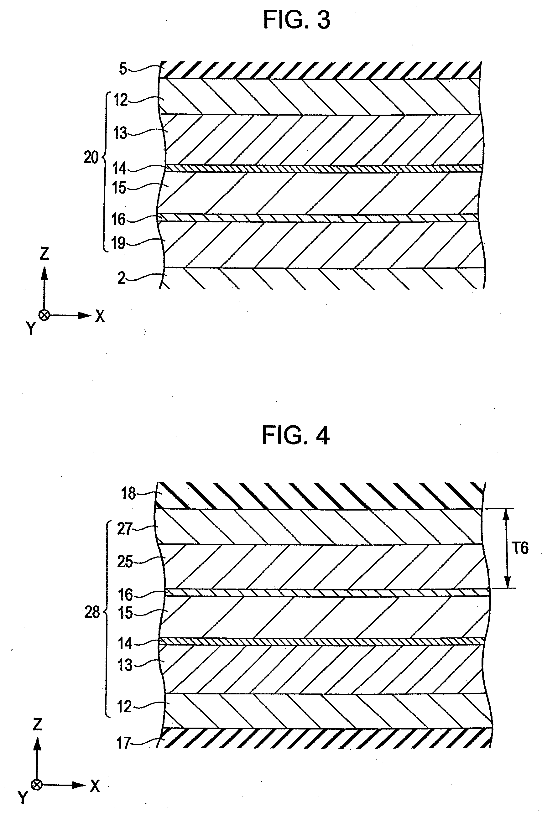
[0011]A tunneling magnetic sensing element according to the present invention includes a laminate including a pinned magnetic layer whose magnetization direction is pinned, an insulating barrier layer, and a free magnetic layer whose magnetization direction varies in response to an external magnetic field disposed in that order from the bottom, or a laminate including the free magnetic layer, the insulating barrier layer, and the pinned magnetic layer disposed in that order from the bottom. The free magnetic layer includes three or more soft magnetic layers; two or more nonmagnetic metal layers, each nonmagnetic metal layer being disposed between two adjacent soft magnetic layers; and an enhancement layer disposed between a first soft magnetic layer and the insulating barrier layer and having higher spin polarizability than each of the soft magnetic layers, the first soft magnetic layer corresponding to one of the soft magnetic layers being provided closest to the insulating barrier layer. Each nonmagnetic metal layer has a thickness that allows the two adjacent soft magnetic layers to be magnetically coupled to each other and allows all the soft magnetic layers to be magnetized in the same direction.
[0012]In the present invention, a nonmagnetic metal layer is disposed between each two adjacent soft magnetic layers constituting a free magnetic layer. The number of soft magnetic layers is three or more, and the number of nonmagnetic metal layers is two or more. Thereby, it is possible to effectively increase the rate of change in resistance (ΔR / R) compared with the known art. According to the experiments which will be described later, in the tunneling magnetic sensing element of the present invention, it is possible to obtain substantially the same RA (element resistance R×area A) as a conventional example in which the nonmagnetic metal layers are not provided in the free magnetic layer or a comparative example in which only one nonmagnetic metal layer is provided between the soft magnetic layers of the free magnetic layer, and a larger rate of change in resistance (ΔR / R) than the conventional example or the comparative example.

Problems solved by technology

If the free magnetic layer has a laminated ferrimagnetic structure, for example, the antiparallel magnetization directions of two magnetic layers facing each other with a nonmagnetic intermediate layer therebetween are disturbed due to a unidirectional bias magnetic field from a hard bias layer placed at each side in the track width direction of the free magnetic layer, and Barkhausen noise is easily caused.

Method used


Image

  • Tunneling magnetic sensing element having free magnetic layer inserted with nonmagnetic metal layers
  • Tunneling magnetic sensing element having free magnetic layer inserted with nonmagnetic metal layers
  • Tunneling magnetic sensing element having free magnetic layer inserted with nonmagnetic metal layers

Examples


example 1

[0088]A tunneling magnetic sensing element including a laminate having a free magnetic layer 6 in which nonmagnetic metal layers 14 and 16 were inserted between a first soft magnetic layer 13 and a second soft magnetic layer 15 and between the second soft magnetic layer 15 and a third soft magnetic layer 19, respectively, as shown in FIG. 2, was fabricated.

[0089]The laminate was formed by depositing, from the bottom, underlying layer 1; Ta(30) / seed layer 2; Ni49at %Fe12at %Cr39at %(50) / antiferromagnetic layer 3; Ir26at %Mn74at %(70) / pinned magnetic layer 4 [first pinned magnetic sublayer 4a; Fe30at %Co70at % (16) / nonmagnetic intermediate sublayer 4b; Ru(8.5) / second pinned magnetic sublayer 4c; Co90at %Fe10at %(18)] / insulating barrier layer 5 / free magnetic layer 6 [enhancement layer 12; Fe90at %Co10at %(10) / first soft magnetic layer 13; Ni88at %Fe12at %(20) / first nonmagnetic metal layer 14; Ta(2.5) / second soft magnetic layer 15; Ni88at %Fe12at %(20) / second nonmagnetic metal layer 16;...

example 2

[0100]A tunneling magnetic sensing element including a laminate having a free magnetic layer 6 in which nonmagnetic metal layers 14 and 16 were inserted between a first soft magnetic layer 13 and a second soft magnetic layer 15 and between the second soft magnetic layer 15 and a third soft magnetic layer 19, respectively, as shown in FIG. 2, was fabricated.

[0101]The laminate was formed by depositing, from the bottom, underlying layer 1; Ta(30) / seed layer 2; Ni49at %Fe12at %Cr39at %(50) / antiferromagnetic layer 3; Ir26at %Mn74at %(70) / pinned magnetic layer 4 [first pinned magnetic sublayer 4a; Fe30at %Co70at %(16) / nonmagnetic intermediate sublayer 4b; Ru(8.5) / second pinned magnetic sublayer 4c; Co90at %Fe10at %(18)] / insulating barrier layer 5 / free magnetic layer 6 [enhancement layer 12; Fe90at %Co10at %(10) / first soft magnetic layer 13; Ni88at %Fe12at %(Y) / first nonmagnetic metal layer 14; Ta(2.5) / second soft magnetic layer 15; Ni88at %Fe12at %(20) / second nonmagnetic metal layer 16; T...


PUM


Abstract

A tunneling magnetic sensing element includes a free magnetic layer disposed on an insulating barrier layer, the free magnetic layer including an enhancement layer, a first soft magnetic layer, a first nonmagnetic metal layer, a second soft magnetic layer, a second nonmagnetic metal layer, and a third soft magnetic layer disposed in that order from the bottom. The enhancement layer is, for example, composed of Co—Fe, each of the soft magnetic layers is, for example, composed of Ni—Fe, and each of the nonmagnetic metal layers is, for example, composed of Ta. Consequently, it is possible to stably obtain a high rate of change in resistance (ΔR / R) compared with the known art.

Description

CLAIM OF PRIORITY[0001]This application claims benefit of the Japanese Patent Application No. 2007-025681 filed on Feb. 5, 2007, the entire content of which is hereby incorporated by reference.BACKGROUND OF THE INVENTION[0002]1. Field of the Invention[0003]The present invention relates to magnetic sensing elements which utilize a tunneling effect and which are to be mounted on hard disk drives and other magnetic sensing devices. More particularly, the invention relates to a tunneling magnetic sensing element in which the rate of change in resistance (ΔR / R) can be increased.[0004]2. Description of the Related Art[0005]In a tunneling magnetic sensing element (TMR element), the change in resistance is caused by a tunneling effect. When the magnetization direction of a pinned magnetic layer is antiparallel to the magnetization direction of a free magnetic layer, a tunnel current does not easily flow through an insulating barrier layer (tunnel barrier layer) provided between the pinned m...

Claims


Application Information

Patent Timeline
IPC IPC(8): G11B5/33
CPCB82Y10/00B82Y25/00G01R33/093G01R33/098H01F10/3295G11B5/3909H01F10/3254H01F10/3272H01L43/08G11B5/3906H10N50/10
Inventor NISHIMURA, KAZUMASANAKABAYASHI, RYOKOBAYASHI, HIDEKAZUNISHIYAMA, YOSHIHIROIDE, YOSUKESAITO, MASAMICHIHASEGAWA, NAOYA
Owner ALPS ALPINE CO LTD
Learn More