Air fuel ratio control apparatus for an internal combustion engine

Active Publication Date: 2008-12-04
MITSUBISHI ELECTRIC CORP
View PDF4 Cites 19 Cited by
  • Summary
  • Abstract
  • Description
  • Claims
  • Application Information

AI Technical Summary

Benefits of technology

[0032]In view of the above, the present invention is intended to obviate the problems as referred to above, and has for its object to obtain an air fuel ratio control apparatus for an internal combustion engine which is capable of achieving control behavior with good stability and response appropriate for a delay in an oxygen storage operation of a catalyst and of always keeping the state of purification of the catalyst in an adequate manner by setting an integral gain for integral calculation in feedback control using a downstream oxygen sensor so as to be proportional to the flow rate of an exhaust gas, and by setting a proportional gain for proportional calculation so as not to be changed due to the exhaust gas flow rate.
[0033]Bearing the above object in mind, an air fuel ratio control apparatus for an internal combustion engine according to the present invention includes: a catalyst that is arranged in an exhaust system of an internal combustion engine for purifying an exhaust gas from the internal combustion engine; an upstream air fuel ratio sensor that is arranged at a location upstream of the catalyst for detecting an air fuel ratio in an upstream exhaust gas upstream of the catalyst; a downstream air fuel ratio sensor that is arranged at a location downstream of the catalyst for detecting an air fuel ratio in a downstream exhaust gas downstream of the catalyst; a first air fuel ratio feedback control section that adjusts an amount of fuel supplied to the internal combustion engine in accordance with the air fuel ratio detected by the upstream air fuel ratio sensor and an upstream target air fuel ratio so as to make the air fuel ratio in the upstream exhaust gas and the upstream target air fuel ratio coincide with each other; and a second air fuel ratio feedback control section that operates, by using at least proportional calculation and integral calculation, the upstream target air fuel ratio in accordance with an air fuel ratio deviation between the air fuel ratio detected by the downstream air fuel ratio sensor and a downstream target air fuel ratio so as to make the detected air fuel ratio of the downstream air fuel ratio sensor and the downstream target air fuel ratio coincide with each other. The second air fuel ratio feedback control section sets an integral gain of the integral calculation to be larger or an update period of the integral calculation to be smaller in accordance with an increasing flow rate of the exhaust gas, so that a change rate of the integral calculation with respect to the air fuel ratio deviation is increased. The second air fuel ratio feedback control section also sets a proportional gain of the proportional calculation so as not to be changed with respect to a change in the flow rate of the exhaust gas.
[0034]According to the present invention, it is possible to achieve control behavior with good stability and response appropriate for a delay in an oxygen storage operation of the catalyst, and it is also possible to always keep the state of purification of the catalyst adequately.

Problems solved by technology

In addition, the upstream oxygen sensor at the upstream side of the catalyst is arranged at a location of an exhaust system as close to combustion chambers as possible (i.e., a merged or collected portion of an exhaust manifold located upstream of the catalyst), and it is subjected to high exhaust temperatures and a variety of kinds of toxic substances, so the output characteristic of the oxygen sensor is caused to vary to a great extent.
That is, at the downstream side of the catalyst, the temperature of the exhaust gas is low, and hence the influence of heat is small, and in addition, various toxic substances are trapped by the catalyst, so the poisoning of the oxygen sensor is small, and the variation of the output characteristic of the oxygen sensor is small.
Accordingly, when the amount of oxygen storage is saturated to the upper limit value or lower limit value (=0), the delay operation to absorb the variation of the upstream air fuel ratio no longer exists, so the air fuel ratio in the catalyst comes off from the stoichiometric air fuel ratio, and the purification ability of the catalyst reduces.
That is, if the individual gains are set to be small, the stability is improved but the response is deteriorated.
In the feedback control using the downstream oxygen sensor, a delay in the oxygen storage operation of the catalyst is very large and predominant in comparison with other delays, and the limit of stability depends on the oxygen storage operation.
This is because the delay in the oxygen storage operation of the catalyst is designed to be sufficiently great so as to absorb the variation of the air fuel ratio due to other delays such as a delay of the oxygen sensor, a delay in movement of the exhaust gas, etc.
In the conventional air fuel ratio control apparatuses for an internal combustion engine, for example in case of the third and fourth patent documents, feedback control is constituted only by integral calculation, so the response of the feedback control is poor in comparison with the case in which integral calculation and proportional calculation are used, thus giving rise to a problem that it is difficult to converge the state of purification of the catalyst deteriorated by external disturbances, etc., into a target value in a swift manner.
In addition, there has also been another problem that even if the integral gain can be set appropriately, the stability of the control system might be deteriorated depending upon the set value of the proportional gain Kp, and hence such a setting does not contribute to a satisfactory solution.
Moreover, in the fifth patent document, the proportional gain and the integral gain are set to be in inverse proportion to the exhaust gas flow rate, so there arises a further problem as stated below.
That is, it is difficult to achieve a control behavior that suits the behavior of the amount of oxygen storage of the catalyst, and in addition, a more complicated construction is required so as to prevent hunting by changing a guard value of the control quantity in proportion to the exhaust gas flow rate, or by providing an intermediate target value.
Thus, with the conventional air fuel ratio control apparatuses for an internal combustion engine, in the so-called PID feedback control using proportional calculation, integral calculation and differential calculation, it is impossible to set a control gain with good stability and controllability appropriate for the delay in the oxygen storage operation of the catalyst, so there is a problem that the state of purification of the catalyst can not be kept adequately with good controllability.

Method used


Image

  • Air fuel ratio control apparatus for an internal combustion engine
  • Air fuel ratio control apparatus for an internal combustion engine
  • Air fuel ratio control apparatus for an internal combustion engine

Examples


embodiment 1

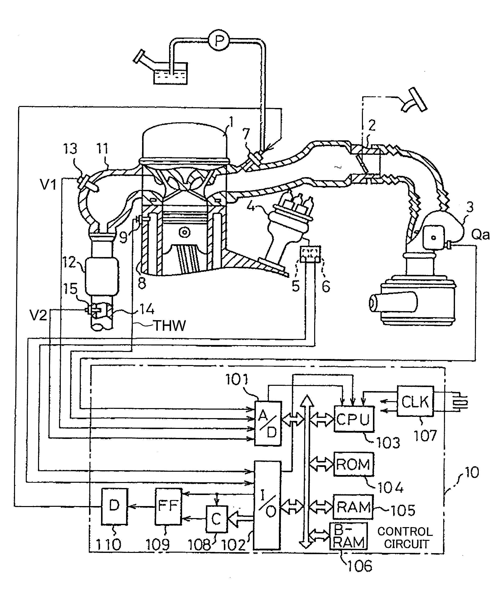
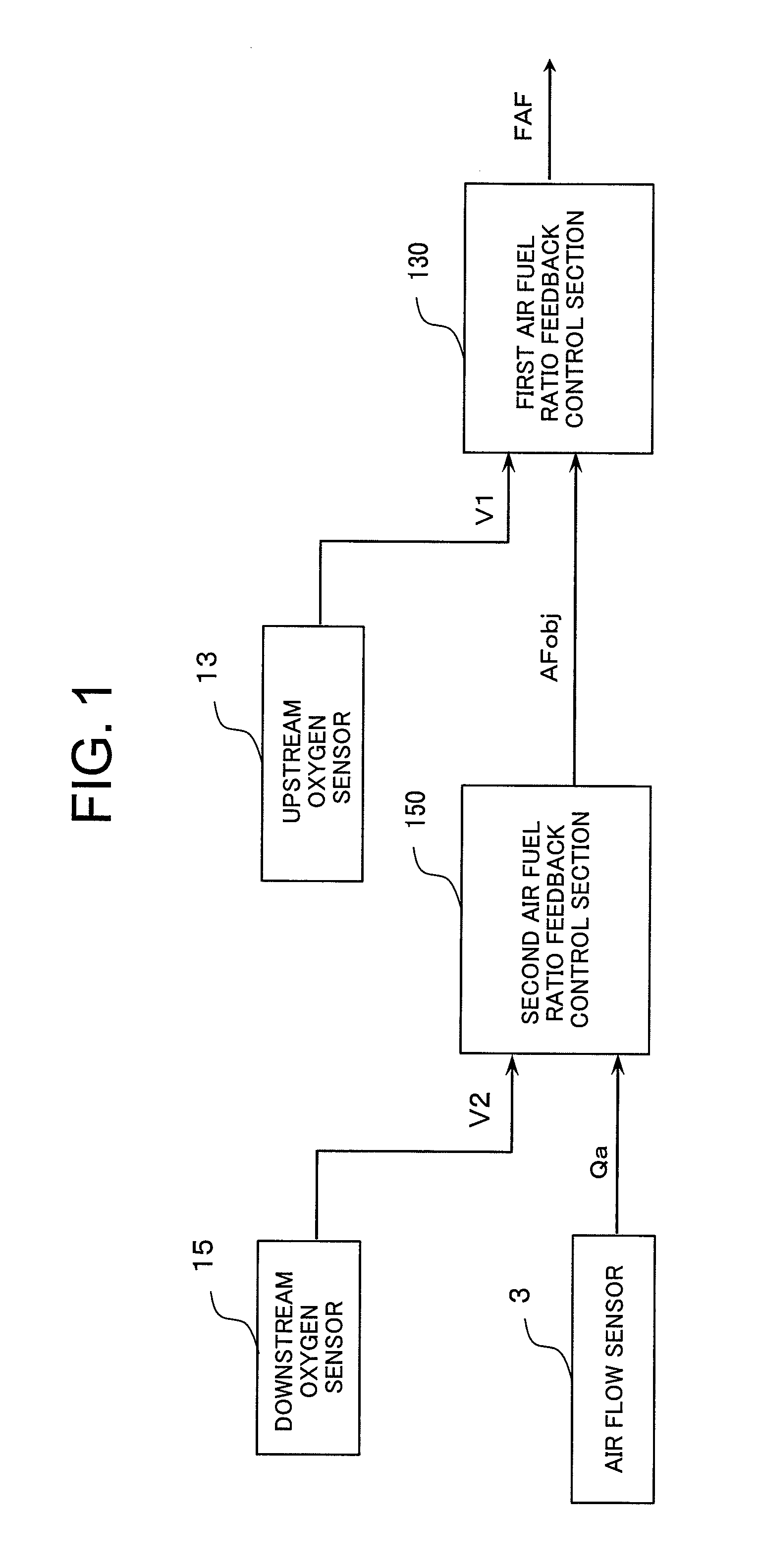
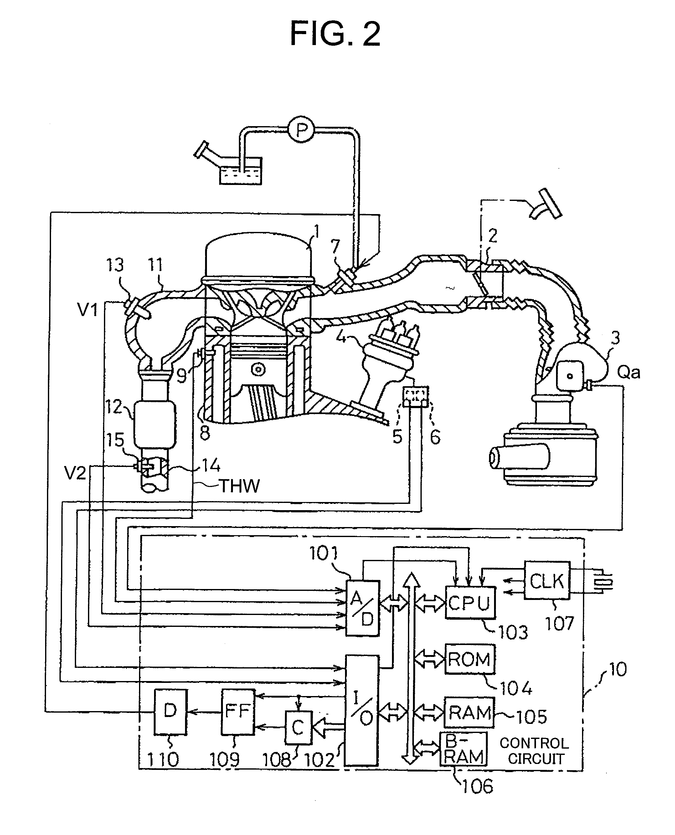
[0059]Referring to the drawings and first to FIG. 1, there is shown, in a block diagram, the construction of sentential portions of an air fuel ratio control apparatus for an internal combustion engine according to a first embodiment of the present invention.

[0060]In FIG. 1, the air fuel ratio control apparatus for an internal combustion engine includes an air flow sensor 3 for detecting an amount of intake air Qa sucked to the internal combustion engine (hereinafter also referred to as an engine), an upstream oxygen sensor 13 disposed at an upstream side of a catalyst, a downstream oxygen sensor 15 disposed at a downstream side of the catalyst, a first air fuel ratio feedback control section 130, and a second air fuel ratio feedback control section 150.

[0061]The first and second air fuel ratio feedback control sections 130, 150 are constituted by a control circuit 10 (to be described later together with FIG. 2). An output value V1 of the upstream oxygen sensor 13 is input to the fi...

embodiment 2

[0228]Although in the above-mentioned first embodiment, a linear type oxygen sensor having a linear output characteristic with respect to a change in the air fuel ratio is used as the upstream oxygen sensor 13, there may be used a λ type oxygen sensor having a binary output characteristic in which its output rapidly changes in the vicinity of the stoichiometric air fuel ratio.

[0229]FIG. 14 is a functional block diagram that shows essential portions of an air fuel ratio control apparatus for an internal combustion engine according to a second embodiment of the present invention, wherein an illustration of the construction thereof similar to that in the above-mentioned first embodiment (see FIGS. 1 and 2) is omitted and those elements corresponding to the above-mentioned ones are identified by the same symbols with “A” attached to their ends.

[0230]In FIG. 14, an upstream oxygen sensor 13A is constituted by a λ type oxygen sensor, and inputs an output value V1 to a first air fuel ratio...


PUM


Abstract

An air fuel ratio control apparatus for an internal combustion engine can achieve control behavior with good stability and response that is appropriate for a delay in an oxygen storage operation of a catalyst, and can always keep the state of purification of the catalyst adequately. The apparatus includes an upstream oxygen sensor (13), a downstream oxygen sensor (15), a first air fuel ratio feedback control section (130) that adjusts an amount of fuel to be supplied so as to make an air fuel ratio in an upstream exhaust gas and an upstream target air fuel ratio (AFobj) coincide with each other, and a second air fuel ratio feedback control section (150) that operates the upstream target air fuel ratio (AFobj) in accordance with an air fuel ratio deviation between an air fuel ratio detected by the downstream oxygen sensor (15) and a downstream target air fuel ratio so as to make the detected air fuel ratio of said downstream oxygen sensor (15) and the downstream target air fuel ratio coincide with each other. The second air fuel ratio feedback control section (150) sets an integral gain of integral calculation to be larger in accordance with an increasing flow rate of the exhaust gas, and also sets a proportional gain of proportional calculation so as not to be changed with respect to a change in the flow rate of the exhaust gas.

Description

BACKGROUND OF THE INVENTION[0001]1. Field of the Invention[0002]The present invention relates to an air fuel ratio control apparatus for an internal combustion engine.[0003]2. Description of the Related Art[0004]In general, a catalytic converter (hereinafter referred to simply as a “catalyst”) with a three-way catalyst received therein for purifying harmful components HC, CO, NOx in an exhaust gas at the same time is installed in an exhaust passage of an internal combustion engine. Since such a kind of catalyst has a high purification rate for any of HC, CO and NOx in the vicinity of a stoichiometric air fuel ratio, an oxygen sensor is generally arranged at an upstream side of the catalyst so that an air fuel ratio of an air fuel mixture is controlled so as to make the air fuel ratio upstream of the catalyst become in the vicinity of the stoichiometric air fuel ratio.[0005]In addition, the upstream oxygen sensor at the upstream side of the catalyst is arranged at a location of an ex...

Claims


Application Information

Patent Timeline
IPC IPC(8): F01N11/00F01N3/20
CPCF02D41/0295F02D41/1441F02D41/1445F02D2041/1409F02D2041/1419F02D2041/1422
Inventor TAKUBO, HIDEKI
Owner MITSUBISHI ELECTRIC CORP
Why Eureka
Try Eureka