Fuel injection valve
- Summary
- Abstract
- Description
- Claims
- Application Information
AI Technical Summary
Benefits of technology
Problems solved by technology
Method used
Image

Examples
Embodiment Construction
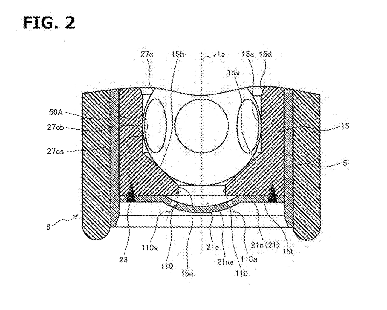
[0027]An embodiment according to the present invention will be explained with reference to FIG. 1 to FIG. 3.
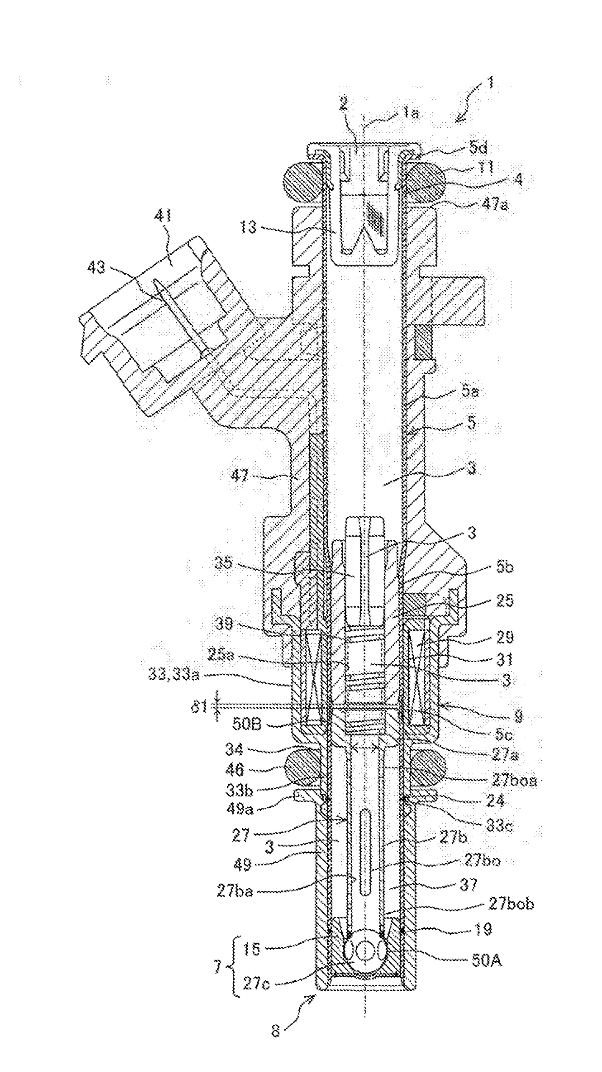
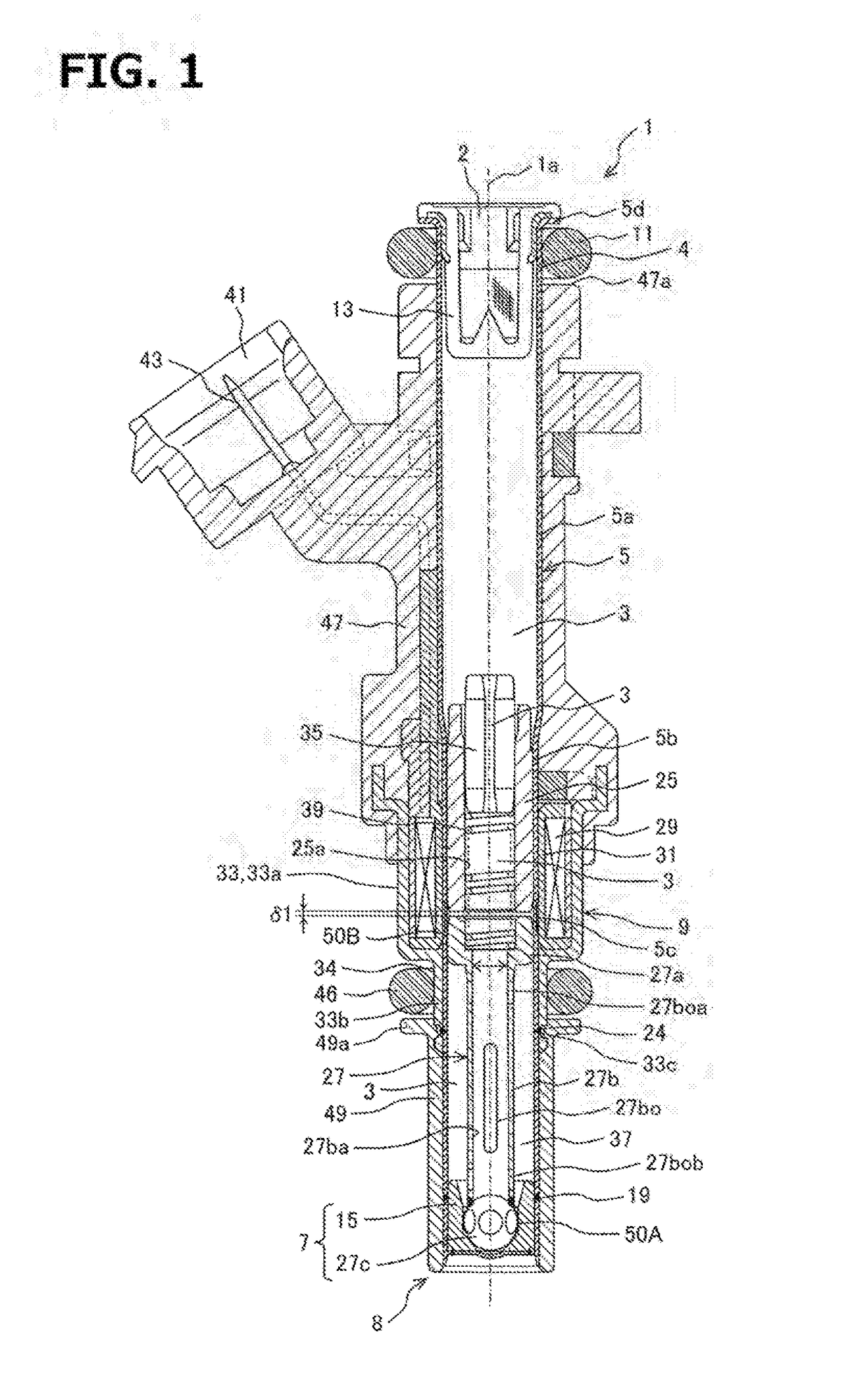
[0028]The whole configuration of a fuel injection valve 1 will be explained with reference to FIG. 1. FIG. 1 is a sectional view showing a cross section along a central axis 1a in one embodiment of the fuel injection valve according to the present invention. In addition, the central axis 1a corresponds to the axis (valve axis) of a movable element (valve assembly) 27 provided integrally with a valve body 27c, a rod part (connection part) 27b and a movable iron core (movable core) 27a, and to the central axis of a cylindrical body 5.
[0029]In FIG. 1, the upper end part (upper end side) of the fuel injection valve 1 is called a base end part (base end side), and the lower end part (lower end side) of the fuel injection valve 1 is called a distal end part (distal end side). The terms “the base end part (base end side)” and “the distal end part (distal end side)” are determined bas...
PUM
 Abstract
Description
Claims
Application Information
 - R&D
- Intellectual Property
- Life Sciences
- Materials
- Tech Scout
- Unparalleled Data Quality
- Higher Quality Content
- 60% Fewer Hallucinations
Browse by: Latest US Patents, China's latest patents, Technical Efficacy Thesaurus, Application Domain, Technology Topic, Popular Technical Reports.
© 2025 PatSnap. All rights reserved.Legal|Privacy policy|Modern Slavery Act Transparency Statement|Sitemap|About US| Contact US: help@patsnap.com