
Recording medium, reproducing apparatus, and reproducing method

a technology of reproducing apparatus and recording medium, which is applied in the direction of recording/reproducing/erasing using optical interference patterns, digital storage, instruments, etc., can solve the problems of difficult to produce a large number of duplicates according to the contact copying process, large size and high cost, and difficult to manufacture hologram readers inexpensively in a simple structure. , to achieve the effect of reducing the distance between the holograms, increasing the recording density, and increasing storage capacity

Inactive Publication Date: 2008-07-31
SONY CORP
View PDF3 Cites 0 Cited by
  • Summary
  • Abstract
  • Description
  • Claims
  • Application Information

AI Technical Summary

Benefits of technology

The solution enables a high-density hologram array with reduced crosstalk, allowing for stable and efficient data reproduction, making it suitable for widespread distribution of computer and AV content data without the need for complex or expensive hardware.

Problems solved by technology

In addition, the shift multiplexing and angle multiplexing processes make it difficult to manufacture hologram readers inexpensively in a simple structure as the processes require reproducing apparatus compatible with them.
For example, if data is recorded in a hologram memory according to the angle multiplexing process, then the hologram reader needs to have a structure for applying a reproducing reference beam at various angles to the hologram memory, and hence is large in size and high in cost.
The shift multiplexing process is also disadvantageous in that it is difficult to produce a large number of duplicates according to a contact copying process.
Though shift multiplexing and angle multiplexing are useful for a system with a very large storage capacity, they are not suitable for a system for distributing a large number of hologram memories to easily provide various data to the general user.
Factors that are to be taken into account in such a recording process are a certain recording density, i.e., a storage capacity, and a crosstalk problem.
Conversely, if element holograms are positioned at sufficiently spaced intervals for reducing crosstalk, then an intermittent signal is produced from the identification patterns and such an intermittent signal is not appropriate as a servo signal.

Method used


Image

  • Recording medium, reproducing apparatus, and reproducing method
  • Recording medium, reproducing apparatus, and reproducing method
  • Recording medium, reproducing apparatus, and reproducing method

Examples


Embodiment Construction

[0045]The embodiments of the present invention will be described below in the following order of topics:

[0046][1. Recording and reproducing process of hologram memory]

[0047][2. Hologram memory according to the embodiment]

[0048][3. Reproducing apparatus arrangement]

[0049][4. Reproducing operation on hologram memory]

1. Recording and Reproducing Process of Hologram Memory

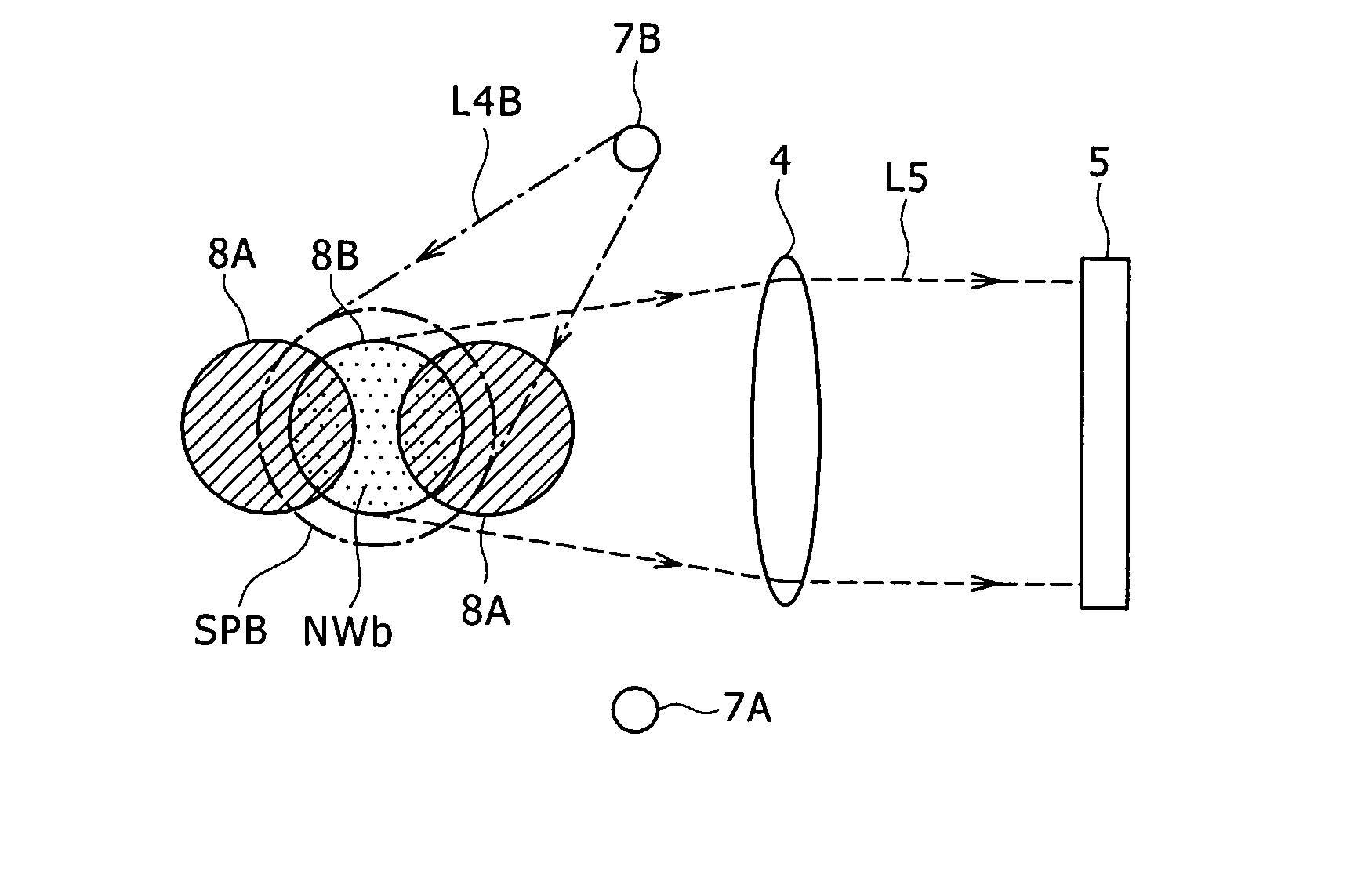
[0050]A basic recording and reproducing process of a hologram memory 3 according to an embodiment will be described below with reference to FIGS. 1A and 1B. FIG. 1A shows the manner in which data is recorded in the hologram memory 3. The data to be recorded is converted into image data in the form of a two-dimensional bar code, for example, as shown, and displayed as a two-dimensional page data image on a liquid crystal panel 1. When a laser beam L1 output from a predetermined light source and converted into a parallel beam passes through the liquid crystal panel 1 with the two-dimensional page data image being display...


PUM


Abstract

A recording medium records therein image data for distributing contents as element holograms with interference fringes generated by interference between an object beam representing the image data and a reference beam. The image data to be distributed which are recorded as the element holograms in the recording medium are reproduced by applying reference beams to the recording medium.

Description

CROSS REFERENCES TO RELATED APPLICATIONS[0001]This application is a divisional of application Ser. No. 11 / 415,157, filed May 2, 2006, which claims priority under 35 U.S.C. 119 to Japanese Patent Application JP 2005-148420 filed in the Japanese Patent Office on May 20, 2005, the entire contents of both of which are being incorporated herein by reference.BACKGROUND OF THE INVENTION[0002]The present invention relates to a recording medium in the form of a hologram for recording data based on fringes produced by interference between an object beam from an image representing the data and a reference beam, and an apparatus for and a method of reproducing data recorded in the recording medium.[0003]There are known in the art holographic recording mediums for recording various data based on fringes produced by interference between an object beam and a reference beam. It is also known in the art that the holographic recording mediums can have a high recording density for large storage capaci...

Claims


Application Information

Patent Timeline
Patent Type & Authority Applications(United States)
IPC IPC(8): G03H1/26
CPCG03H1/26G11C13/042G11B7/007G11B7/0065
Inventor TERAOKA, YOSHIYUKI
Owner SONY CORP
Learn More