Liquid crystal display panel
a liquid crystal display and panel technology, applied in non-linear optics, instruments, optics, etc., can solve the problems of insufficient wideness of conventional liquid crystal displays, improve the problem of poor liquid crystal arrangement or low aperture ratio, and reduce the quantity of protruding protruding
- Summary
- Abstract
- Description
- Claims
- Application Information
AI Technical Summary
Benefits of technology
Problems solved by technology
Method used
Image
Examples
first embodiment
[0030]Please refer to FIG. 3. FIG. 3 illustrates a cross-sectional view of an MVA LCD panel 40 according to the first embodiment of the present invention. As shown in FIG. 3, the MVA LCD panel 40 includes a top substrate 42, a bottom substrate 44, a liquid crystal layer 46 disposed between the top substrate 42 and the bottom substrate 44, a common electrode 48 disposed on the top substrate 42, a color filter 45 disposed between the top substrate 42 and the common electrode 48, a plurality of protrusions 52 disposed on the common electrode 48, and a plurality of thin film transistors (not shown) and pixel electrodes 58 disposed on the bottom substrate 44. The liquid crystal layer 46 can be composed of negative or positive liquid crystals. Alternatively, the color filter 45 can be formed on the bottom substrate 44 to form a color filter on array substrate, which are all within the scope of the present invention.
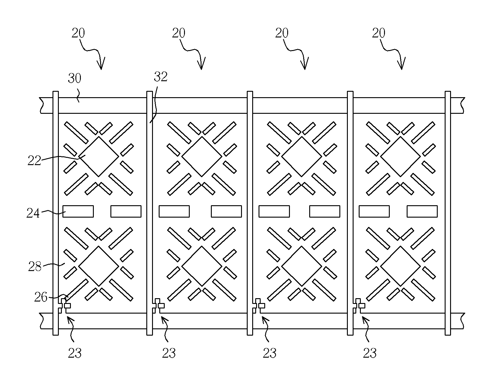
[0031]Please refer to FIGS. 4-6. FIG. 4 illustrates a plan view of a pixel...
second embodiment
[0033]Please refer to FIG. 7. FIG. 7 illustrates a plan view of a pixel unit 80 of the MVA LCD panel according to the second embodiment of the present invention. As shown in FIG. 7, the MVA LCD panel includes a pixel unit 80, a plurality of scan lines 82 and data lines 84 disposed around the pixel unit 80, and a plurality of protrusions 86 disposed on the top substrate where correspond to the scan lines 82 and data lines 84. The pixel unit 80 is driven by a switch element 83 electrically connected to the scan lines 82, the data lines 84, and the pixel electrode 88, in which the switch element 83 is preferably a thin film transistor.
[0034]The pixel unit 80 includes a pixel electrode 88 having a plurality of main slits 89. Depending on the design of the product, the main slits 89 can be formed in the pixel electrode 88 or extended to the edge of the pixel electrode 88. In contrast to the first embodiment, the left protrusions 86 of the second embodiment are positioned corresponding to...
third embodiment
[0035]Please refer to FIG. 8. FIG. 8 illustrates a plan view of a pixel unit 90 of the MVA LCD panel according to the third embodiment of the present invention. As shown in FIG. 8, the MVA LCD panel includes a pixel unit 90, a plurality of scan lines 92 and data lines 94 disposed around the pixel unit 90, and a plurality of protrusions 96 disposed on the top substrate where correspond to the scan lines 92 and data lines 94. The pixel unit 90 is driven by a switch element 93 electrically connected to the scan lines 92, the data lines 94, and the pixel electrode 98, in which the switch element 93 is preferably a thin film transistor.
[0036]The pixel unit 90 includes a pixel electrode 98 having a plurality of main slits 97 and fine slits 99. Depending on the design of the product, the main slits 97 and the fine slits 99 can be formed in the pixel electrode 98 or extended to the edge of the pixel electrode 98. Similar to the second embodiment of the present invention, the left protrusion...
PUM
 Abstract
Description
Claims
Application Information
 - R&D
- Intellectual Property
- Life Sciences
- Materials
- Tech Scout
- Unparalleled Data Quality
- Higher Quality Content
- 60% Fewer Hallucinations
Browse by: Latest US Patents, China's latest patents, Technical Efficacy Thesaurus, Application Domain, Technology Topic, Popular Technical Reports.
© 2025 PatSnap. All rights reserved.Legal|Privacy policy|Modern Slavery Act Transparency Statement|Sitemap|About US| Contact US: help@patsnap.com


