
Method for preventing siphoning effect in terminal and terminal manufactured using the same

Inactive Publication Date: 2008-07-31
LOTES
View PDF9 Cites 6 Cited by
  • Summary
  • Abstract
  • Description
  • Claims
  • Application Information

AI Technical Summary

Benefits of technology

[0007]A scope of the invention is to provide a method for preventing siphoning effect during the process of welding a terminal onto a printed circuit board and the terminal manufactured using the method.
[0008]In order to realize the aforesaid scope, the invention provides a method for preventing siphoning effect during the process of welding a terminal onto a printed circuit board. The terminal comprises a conductive portion connected to an external component by a solder and a connecting portion extending from the conductive portion. Moreover, a copper coating, which is exposed and easily oxidized, is electroplated on the surface of the connecting portion and the copper can be further oxidized to form a copper oxide.
[0010]Since the copper, which is exposed and easily oxidized, is electroplated on the connecting portion of the terminal of the invention, and a copper oxide will be formed outside surface of the connecting portion which can prevent the siphoning of solder from the conductive portion of the terminal to the connecting portion of the terminal during the process of soldering the terminal. Therefore, it is very helpful in saving solder, in preventing the occurrence of missing solder, in ensuring the soldering quality, and in facilitating the saving of production cost.

Problems solved by technology

Since the surface of the conductive terminal is electroplated with gold and very fine part can be easily generated on the gold-electroplated layer, siphoning effect will be generated during the process of soldering the conductive terminal, and the melted solder will be siphoned from the soldering end of the conductive terminal to the contact portion of the conductive terminal, which in turn leads to massive loss of the solder and the so-called false welding.
The aforesaid effect will seriously affect the electrical connection between the conductive terminal and the printed circuit board.

Method used


Image

  • Method for preventing siphoning effect in terminal and terminal manufactured using the same
  • Method for preventing siphoning effect in terminal and terminal manufactured using the same

Examples


Embodiment Construction

[0013]In the following, the attached figures will be associated to describe the method of the invention capable of preventing the occurrence of siphoning effect in the terminal and the terminal is manufactured using the method.

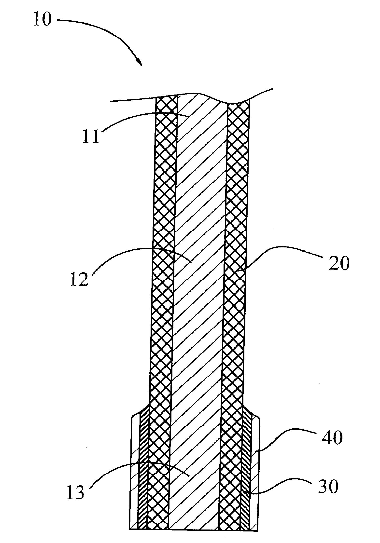
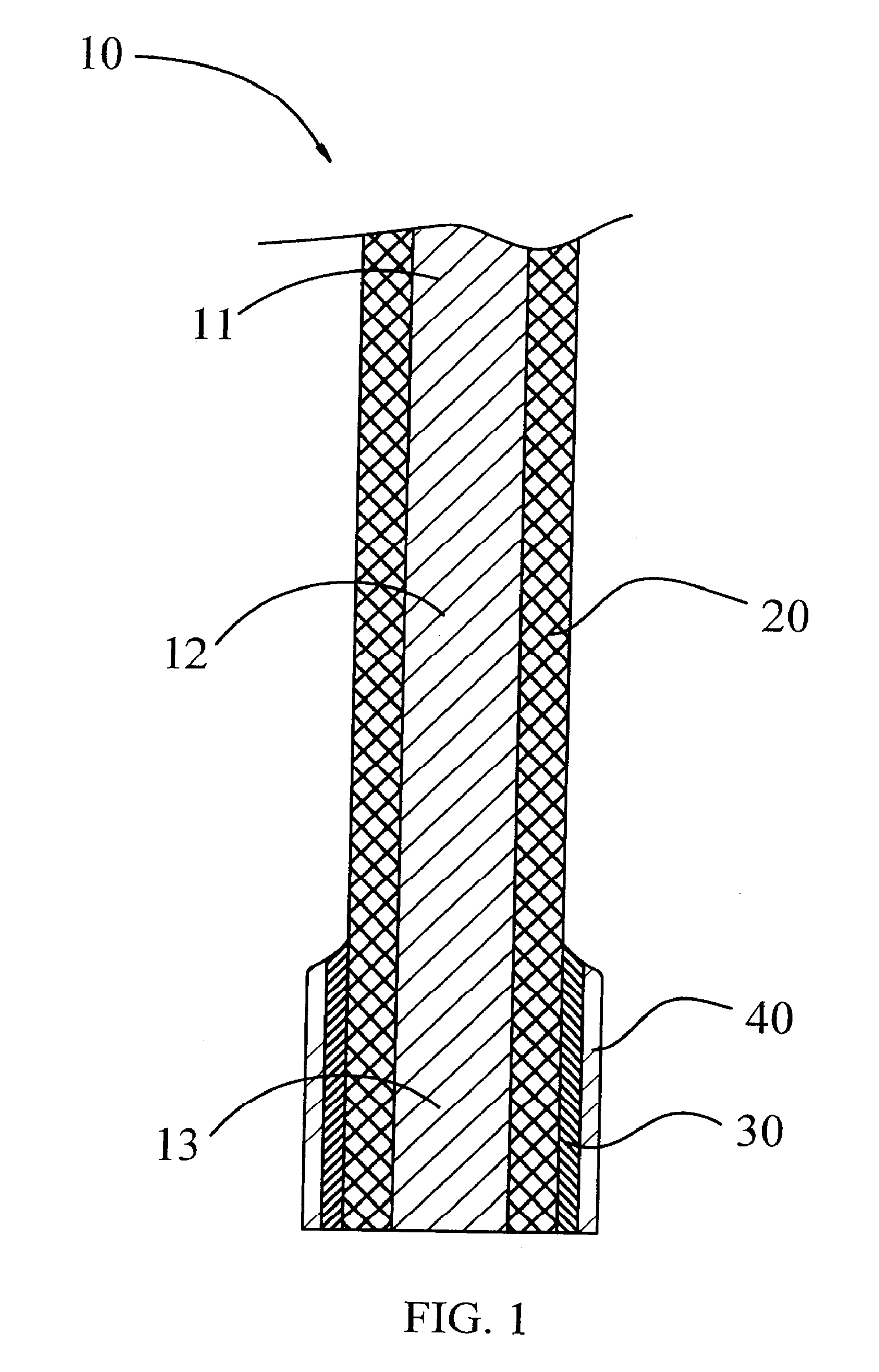
[0014]Please refer to FIG. 1. FIG. 1 is a schematic diagram illustrating parts of the terminal 10 in the present invention capable of preventing siphoning effect. The terminal 10 includes a conductive portion 13 soldered to an external component (such as a printed circuit board) by a solder (not shown in FIG. 1), and a connecting portion 12 extending from the conductive portion 13. The connecting portion 12 further extends to form a contact portion 11 (in FIG. 1, only part of the contact portion 11 is shown). The contact portion 11 is used to electrically contact a chip module (not shown in FIG. 1), an interface card (not shown in FIG. 1), or other electronic components (not shown in FIG. 1) to a printed circuit board (not shown in FIG. 1). The surface of the ...


PUM

PropertyMeasurementUnit
Electrical conductoraaaaaaaaaa

Abstract

The invention relates to a method for preventing siphoning effect in a terminal. The terminal of the invention comprises a conductive portion connected to an external component by a solder and a connecting portion extended to form the conductive portion. An exposed and easily oxidized copper is attached on the surface of the connecting portion, and the copper can be further oxidized to form oxide of copper. Since the copper is attached on the connecting portion of the terminal, and the copper can be oxidized to form oxide of copper, the oxide of copper, such as copper oxide, can prevent the siphoning of the solder from the conductive portion to the connecting portion during the soldering process. Accordingly, the solder can be saved, and the phenomenon of false welding can be avoided, such that the quality of soldering can be maintained well and the production cost can be reduced.

Description

BACKGROUND OF THE INVENTION[0001]1. Field of the Invention[0002]The present invention relates to a method for preventing siphoning effect in a terminal and the terminal is manufactured using the method.[0003]2. Description of the Prior Art[0004]Currently, an electrical connector is usually used to electrically connect an electronic component, such as a chip module or an interface card, to a printed circuit board, and such electrical connector is usually equipped with conductive terminals. Moreover, one end of the conductive terminal (i.e. the contact portion) is electrically connected to the electronic component and the other end (i.e. the soldering end) is soldered to the printed circuit board, so as to fulfill the electrical connection between the electronic component and the printed circuit board.[0005]A current method of soldering a conductive terminal onto a printed circuit board including following steps: planting a solder ball onto the soldering end of the conductive terminal...

Claims


Application Information

Patent Timeline
IPC IPC(8): H01B5/00B05D5/00C25D7/00
CPCC25D5/12H01R4/028C25D7/00
Inventor JU, TED
Owner LOTES
Learn More