Bone dilator
- Summary
- Abstract
- Description
- Claims
- Application Information
AI Technical Summary
Benefits of technology
Problems solved by technology
Method used
Image
Examples
Embodiment Construction
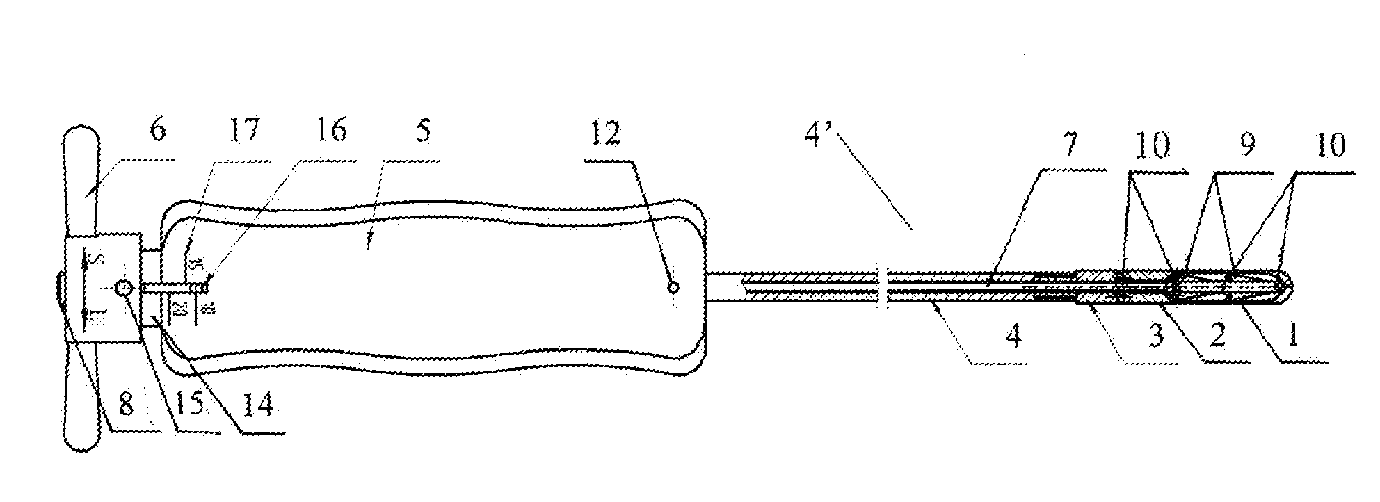
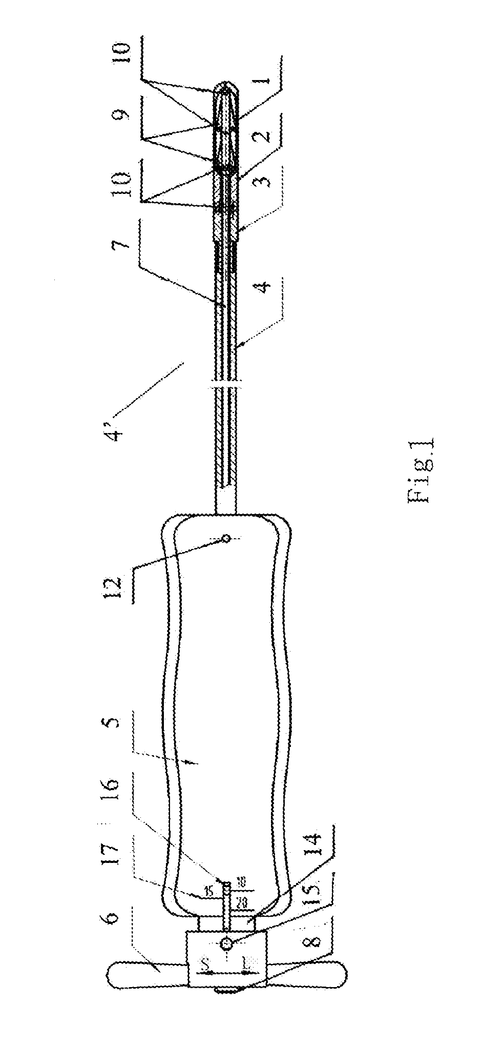
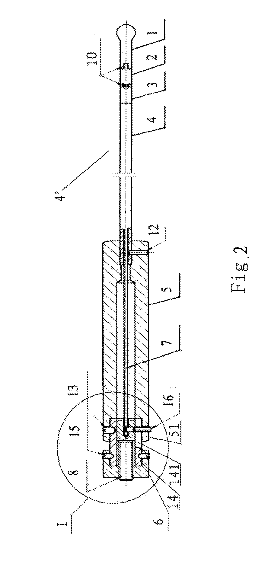
[0020]For illustration purpose, the right sides in FIGS. 1 and 2 are referred to as distal ends or fronts, and the left sides are referred to as proximal ends or rears.
[0021]In FIGS. 1-4, specific embodiments of the bone dilator according to the present invention are described in greater detail. The structure of the bone dilator according to the present invention comprises a head portion 1, a neck portion 2, a connecting tube 4′, a handle 5, and a rotary hilt 6. The head portion 1, the neck portion 2, the connecting tube 4′ and the handle 5 are all arranged as hollow bodies, through which a pull rod 7 penetrates. The head portion 1 and the neck portion 2 are integrated as a whole via hinged joint therebetween. At the center of the rotary hilt 6 is disposed a tension bolt 8, which is connected to a proximal end of the pull rod 7.
[0022]To make it easier for fabrication, the connecting tube 4′ can also consist of a connecting tube body 4 and a waist portion 3, and such a combination ha...
PUM
 Abstract
Description
Claims
Application Information
 - R&D
- Intellectual Property
- Life Sciences
- Materials
- Tech Scout
- Unparalleled Data Quality
- Higher Quality Content
- 60% Fewer Hallucinations
Browse by: Latest US Patents, China's latest patents, Technical Efficacy Thesaurus, Application Domain, Technology Topic, Popular Technical Reports.
© 2025 PatSnap. All rights reserved.Legal|Privacy policy|Modern Slavery Act Transparency Statement|Sitemap|About US| Contact US: help@patsnap.com


