
Polymer electrolyte fuel cell

a fuel cell and electrolyte technology, applied in the field of polymer electrolyte fuel cells, can solve the problems of shortening the life of the cell, increasing the amount of gas consumption, and accumulating waterdrops

Inactive Publication Date: 2008-07-10
HITACHI LTD
View PDF4 Cites 2 Cited by
  • Summary
  • Abstract
  • Description
  • Claims
  • Application Information

AI Technical Summary

Benefits of technology

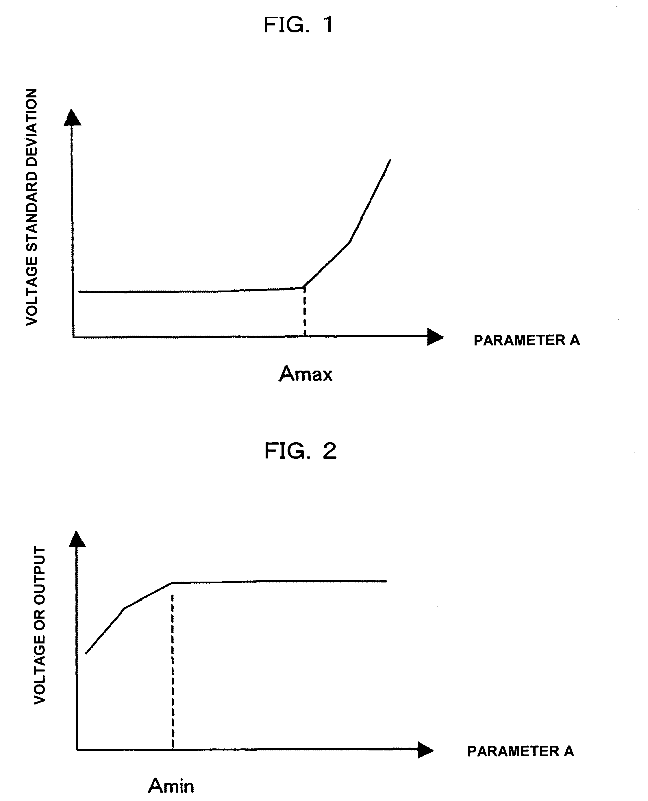
[0016]In contrast, the output depends on a water content of an electrolyte membrane (including electrolyte material of a catalyst layer). Membrane resistance decreases with increasing water content, making ionic migration easier. As a result, the cell voltage improves with higher output. Conversely, if the water content decreases, the output also decreases. The water content also depends on the amount of water present inside a cell.
[0035]According to the present invention, output improvement of a fuel cell can be combined with voltage stability.

Problems solved by technology

If the voltage of each cell becomes unstable, a main cause thereof is that waterdrops accumulate in a gas passage inside the cell and a blockade of the passage or flooding (wetting) on an electrode surface inhibits a hydrogen oxidization reaction or oxygen reduction reaction on the electrode.
If the aforementioned reaction inhibition occurs, an undesirable reaction such as catalyst dissolution and oxidization of a conducting material proceeds to the extent that a current fed by electricity generation to flow through each cell exceeds the amount of gas consumption.
As a result, deterioration of the catalyst and an increase in contact resistance caused by oxidization of separators will occur, making the life of the cell shorter in the end.
There is also a problem of malfunction in which the voltage becomes unstable due to water transiently stored in a cell after variations of the temperature or output of the cell not only during electricity generation at rated power output, but also during startup or load change.
In this case, a side reaction caused by a passage blockade will oxidize or corrode material of, for example, the electrode catalyst and separators, making the cell life shorter.
However, simply lowering the gas dew point decreases the amount of water taken in a cell, decreasing the probability of occurrence of a passage blockade, but, on the other hand, adverse effects such as decreased water content of an electrolyte membrane, an output drop due to increased ionic resistance, and further a drop in cell life due to a gas cross via the electrolyte membrane may be caused.

Method used


Image

  • Polymer electrolyte fuel cell
  • Polymer electrolyte fuel cell
  • Polymer electrolyte fuel cell

Examples


first embodiment

[0040]The first embodiment is realized by an operation map stipulated by parameters described below.

[0041]The number of cells in a fuel cell is specific to cell specifications such as the cell output, current, and operating temperature. If the number of cells is determined, the number of separators is also determined and therefore, the volume of a gas passage of the separators and the surface area of the gas passage are determined by the cell specifications. Water accumulated inside the passage while electricity being generated depends on the surface area of the passage because it is attached to the surface of the passage. Water accumulated inside the passage while electricity being generated also depends on the shape of the passage because the ease with which the water is discharged is controlled by the linear velocity (defined as the flow rate / passage cross section) of a gas flowing through the passage. As a result, the probability of occurrence of a passage blockade is specific t...

second embodiment

[0060]The second embodiment is a fuel cell system, wherein if the temperature (Tmax) at which the standard deviation of the cell voltage begins to increase when the gas dew point is increased under conditions under which the cell temperature, gas entrance dew point, and current are specified and the temperature (Tmin) at which the average value of the cell voltage begins to drop when the gas dew point is decreased under conditions under which the cell temperature, gas entrance dew point, and current are specified are defined, the gas entrance dew point (water feeding speed to the cell) at startup satisfies: upper limit of the maximum amount of water retained in a cell≧(cell temperature−gas entrance dew point)×gas flow rate×startup time+water generation speed×startup time. This is an operation condition particularly focusing on voltage stabilization at startup when the gas entrance dew point is selected as the first voltage stabilization control parameter. In this case, the cell temp...

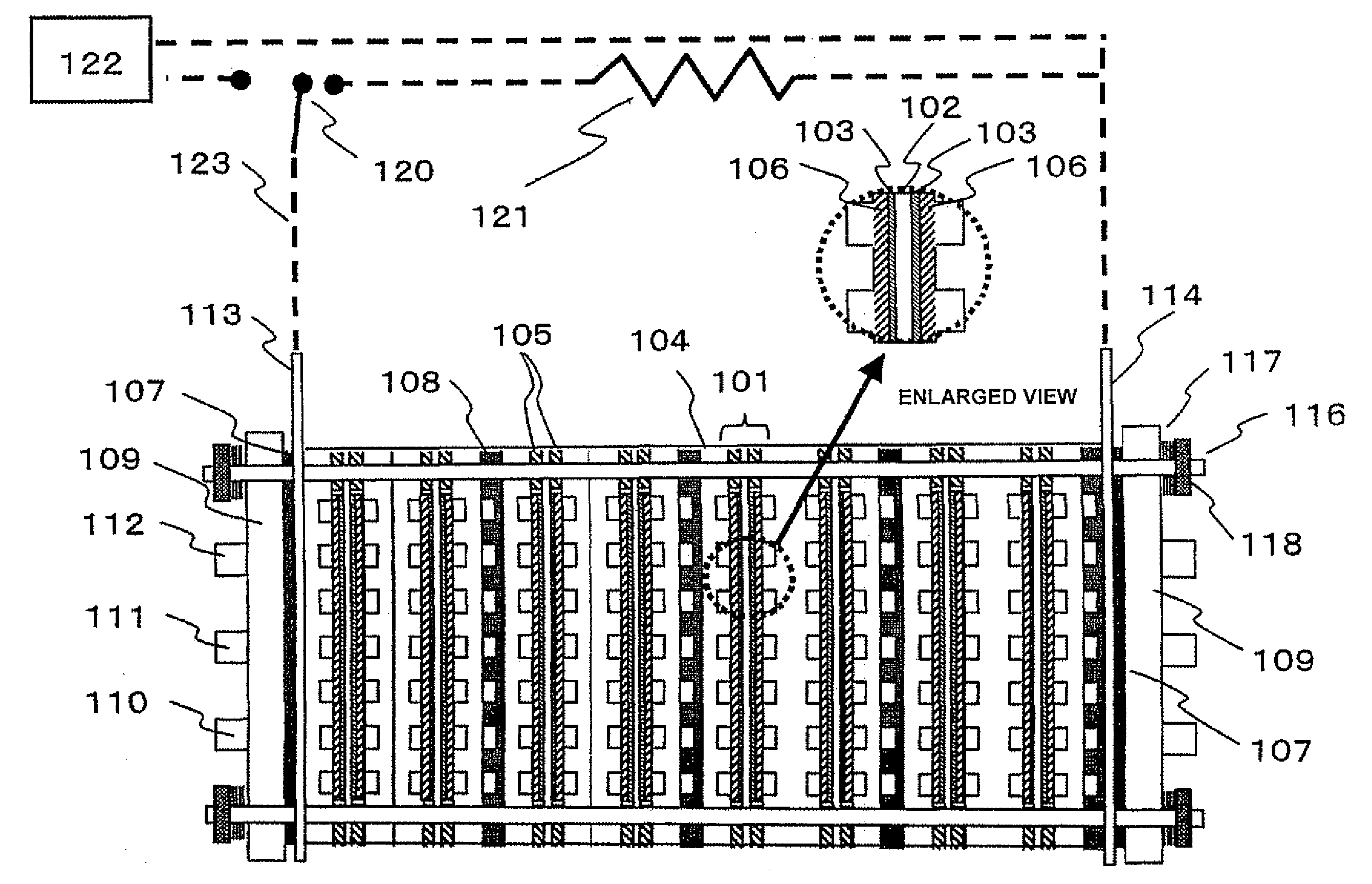
fifth embodiment

[0067]The fifth embodiment is a fuel cell system provided with a function for controlling an electricity generation control method by which Tmax is caused to change by making a coordinated operation to be performed between rate of revolutions (=gas flow rate) of a circulating pump and a gas feed pump and the fuel cell. If the rate of revolutions of the gas feed pump is increased, the gas linear velocity increases in a separator passage, making a passage blockade more unlikely. Thus, the gas dew point can be increased to a higher value, which is an effective means when a passage blockade is likely to occur at startup or when the load changes.

[0068]The sixth embodiment is a fuel cell system provided with a function for controlling an electricity generation control method by which Tmax is caused to change by making a coordinated operation to be performed between a secondary battery and the fuel cell. This is intended to relatively lower electric power of a polymer electrolyte fuel cell...


PUM


Abstract

An object of the present invention is to provide a polymer electrolyte fuel cell capable of producing a high output without causing a drop or instability of the cell voltage of the fuel cell and a generating system having the polymer electrolyte fuel cell mounted thereon.A fuel cell system, wherein if, in a polymer electrolyte fuel cell having a cell comprising separators sandwiching an electrolyte membrane and electrodes, a temperature (Tmax) at which a standard deviation of a cell voltage begins to increase when water content retained in the cell is increased under conditions under which a cell temperature, a gas entrance dew point, and a current are specified and the temperature (Tmin) at which an average value of the cell voltage begins to drop when the gas dew point is decreased under conditions under which the cell temperature, gas entrance dew point, and current are specified are defined, the water content retained in the cell satisfies: upper limit of a maximum amount of water retained in a cell≧water content retained in a cell≧lower limit of a maximum amount of water retained in a cell is provided.

Description

BACKGROUND OF THE INVENTION[0001]1. Field of the Invention[0002]The present invention relate to a startup time reduction or output characteristic stabilization of a polymer electrolyte fuel cell and a generating system having the polymer electrolyte fuel cell mounted thereon by preventing malfunctions such as instability of a voltage of the polymer electrolyte fuel cell and a voltage drop when the fuel cell starts up, electricity is generated steadily, or a load changes.[0003]2. Description of the Related Art[0004]Due to a high output, long life, less deterioration by startup / stop, low operating temperature (about 70 to 80° C.) and the like, a polymer electrolyte fuel cell has advantages such as ease of startup / stop. Therefore, wide-ranging uses such as a power supply for electric vehicles and a dispersed power supply for businesses and homes are expected.[0005]Among such uses, a dispersed power supply (for example, a cogeneration generating system) in which polymer electrolyte fuel...

Claims


Application Information

Patent Timeline
IPC IPC(8): H01M8/04H01M8/10
CPCH01M8/04007H01M8/04097H01M8/04179Y02E60/50H01M8/04291H01M16/006H01M8/04223H01M8/04225H01M8/04302Y02E60/10
Inventor NISHIMURA, KATSUNORISASAKI, HIRONORIYAMAGA, KENJI
Owner HITACHI LTD
Learn More