
Receiver For Optical Communications, Comprising a Nonlinear Equaliser

a nonlinear equalizer and optical communication technology, applied in electromagnetic receivers, electrical apparatus, electromagnetic transmission, etc., can solve the problems of unsatisfactory or exact practicability of the block implementation with electrical or electronic circuitry, and achieve the effect of reducing the negative effects of such distortion, enhancing the advantages of electronic equalization systems, and increasing the maximum optical fibre link length

Inactive Publication Date: 2008-07-03
UNIV POLITECNICA DE CATALUNYA
View PDF5 Cites 3 Cited by
  • Summary
  • Abstract
  • Description
  • Claims
  • Application Information

AI Technical Summary

Benefits of technology

[0012]The inclusion of this non-linear equalizer block in the optical receiver after the photo-detector block may enhance the advantages of the electronic equalization system by compensating for linear distortions in the transmission. This may be performed in the final processor block which may use algorithms of signal processing technologies, analog or digital. These may include a transversal linear filter, a “feed-forward” equalizer, a “decision-feedback” equalizer, a “maximum likelihood sequence estimator”, or combinations of the foregoing among others. There may also be one or more or several delay and / or multiplier stages with configurable coefficients or weights.
[0013]These algorithms theoretically allow for compensation of any linear distortion and thus, potentially, mitigate or eliminate the negative effects of such distortion. However, the non-linear characteristics of the photo-detector may turn a linear distortion into a non-linear distortion which may also be mitigated.

Problems solved by technology

This relation is theoretical and ideal, and the practical implementation of the block with electrical or electronic circuitry is not normally ideal or exact.

Method used


Image

  • Receiver For Optical Communications, Comprising a Nonlinear Equaliser
  • Receiver For Optical Communications, Comprising a Nonlinear Equaliser

Examples


Embodiment Construction

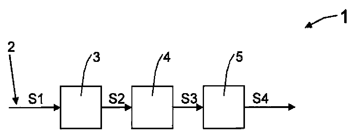
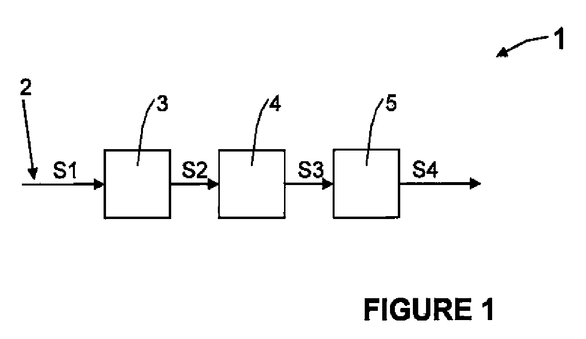
[0021]As can be seen in FIG. 1, the optical communication receiver 1 may have a first element of entrance of an optical fibre 2 by which an information carrying signal S1 may be transmitted, an optical detector block 3, a non-linear equalizer block 4 and a final processor block 5.

[0022]The optical signal S1 which may be a carrier of information, may be transmitted along the optical fibre 2 and may have originated at a remote optical transmitter (not shown). This signal S1 may be introduced into the optical photo-detector detector block 3, which may generate an electrical signal S2 that may be introduced into the non-linear equalizer block 4. This block 4 may generate, from S2, the S3 signal, which may be later equalized and filtered by the final processor block 5, which may generate the output signal S4.

[0023]The present development may include a non-linear equalizer block 4, which may produce a signal S3 that is proportional to the mathematical square root of its input signal S2.

[0...


PUM


Abstract

The present development includes a first element of an optical fibre entrance by which an information carrying signal is transmitted, an optical detector block, a non-linear equalizer block and a final processor block. The development includes an electrical non-linear equalizer block, connecting the output of the optical detector block and the input of the final processor block that compensates the quadratic non-linear characteristic of the optical detector block. Both blocks thus may present a more linear joint characteristic between the electrical field envelope of the information carrying signal in the optical fibre and the electrical signal. Consequently, the final processor block can compensate, in a more effective form, for the linear distortions that the information carrying signal suffers in the transmission through the fibre. The result may be an optical receiver with non-linear compensation of the photo-detection process and with approximate linear compensation of the linear distortions of the optical fibre transmission.

Description

[0001]The present development relates to a receiver for optical communications with a first element of an optical fibre entrance, through which an information signal is transmitted, an optical detection block, a non-linear equalizer block, and a final processor block.BACKGROUND [0002]Due to progress in the fields of laser beams and of optical fibres, communication systems with optical fibres as transmission channels are possible, and depend fundamentally on the characteristics of light.[0003]A communication system with an optical fibre, may have an emission block, also called emitter or optical transmitter, that has the ability to transform an information electrical signal into an information signal in light form; a transmission channel of this light, i.e. an optical fibre; and a reception or receiver block, that has the ability to transform the received optical information into information in the form of an electrical signal. The reception block with or without other devices may be...

Claims


Application Information

Patent Timeline
IPC IPC(8): H04B10/06H04B10/69
CPCH04B10/6971
Inventor PRAT GOMA, JOSEPPOGGIOLINI, PIERLUIGI
Owner UNIV POLITECNICA DE CATALUNYA
Learn More