
Radio Identification With an Additional Close-Range Check

Active Publication Date: 2008-07-03
NXP BV
View PDF20 Cites 30 Cited by
  • Summary
  • Abstract
  • Description
  • Claims
  • Application Information

AI Technical Summary

Benefits of technology

[0035]One advantageous measure for increasing the security is that, in order to carry out the close-range check, a time window is predefined for detecting the close-range status signal following activation of the transponder.
[0036]A further advantageous measure for increasing the security is that a coded close-range status signal is provided.
[0037]Another advantageous measure for increasing the security is that a change in the coding of the close-range status signal is provided after each successful identification.
[0039]A further advantageous measure for increasing the security is that a variable close-range status signal is provided (e.g. a magnetic field with changing polarization).

Problems solved by technology

Like all identification systems which operate on the basis of digital data, radio identification systems are also at risk of so-called brute force attacks and / or dictionary attacks.
However, one fundamental risk in terms of security against misuse of radio identification systems consists in the lack of a physical presence check of the authorized key.
This risk of misuse is moreover particularly high in those radio identification systems in which no additional manual activation of the transponder is required for radio identification.

Method used


Image

  • Radio Identification With an Additional Close-Range Check
  • Radio Identification With an Additional Close-Range Check
  • Radio Identification With an Additional Close-Range Check

Examples


Embodiment Construction

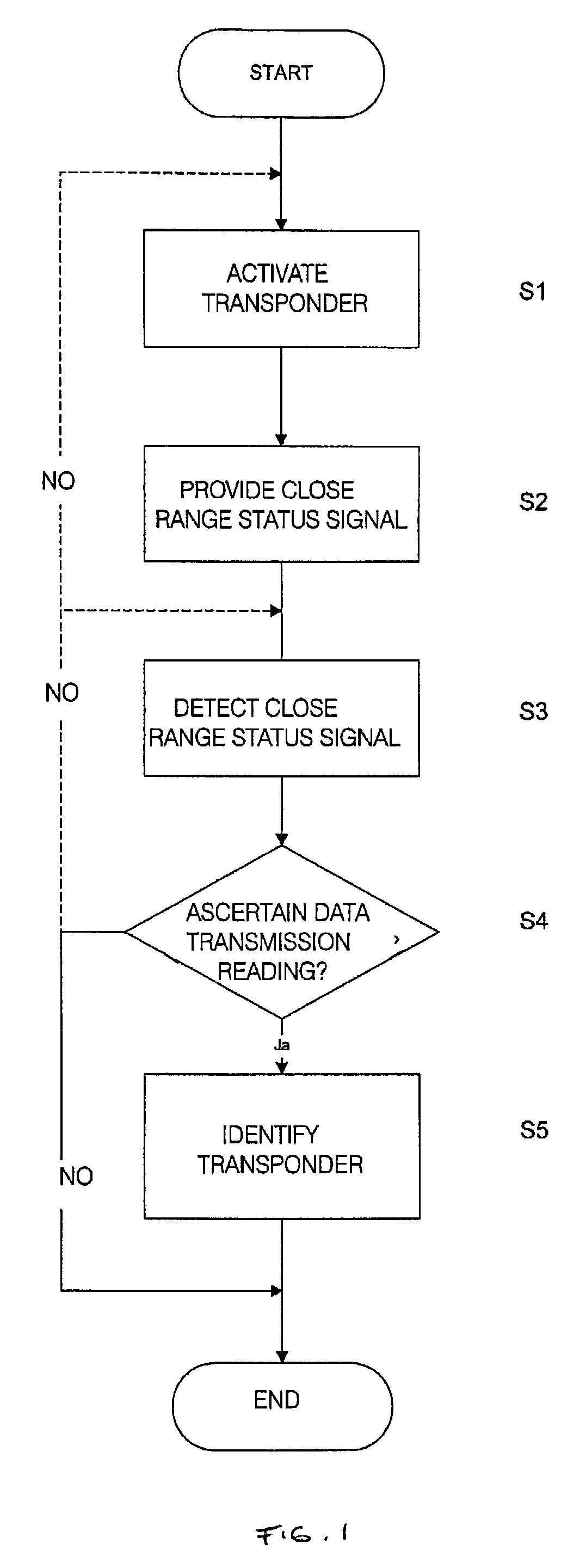
[0047]Firstly, one possible example of embodiment of the method according to the invention will be described with reference to FIG. 1. As shown in FIG. 1, the radio identification method according to the invention proceeds as follows:

[0048]Step S1: Following activation of the reader, the latter transmits a high-frequency signal for activating the transponder (activation signal). When the transponder receives this activation signal, it becomes activated for radio identification in step S1.

[0049]Step S2: The transponder is then in principle activated for radio transmission; however, its data for the identification cannot yet be transmitted since no additional close-range check has yet taken place. To this end, in step S2, a close-range status signal is provided in the close range of the reader, which close-range status signal indicates the close range of the reader.

[0050]Step S3: The close-range status signal is detected by the transponder.

[0051]Step S4: In step 4, a check is made to ...


PUM


Abstract

The invention relates to a method and a system for radio identification with an additional close-range check, which prevent misuse of a radio identification system and increase the security of radio identification. In particular, so-called relay attacks are to be largely prevented in passive entry systems. The method according to the invention firstly provides for activation of a transponder (S1) for reading of its data. After this step, an additional close-range status signal is provided (S2) which indicates the close range of a reader. Once the close-range status signal has been detected by a transponder (S3), data transmission for reading of the data stored in the transponder by the reader is possibly enabled in reaction to the detection of the close-range status signal (S4) and the data can be read by the reader for identification of the transponder (S5). The system according to the invention for radio identification with an additional close-range check consists of a reader for reading the data stored in a transponder and of an evaluation unit which is connected to the reader for identifying the transponder on the basis of the read data.

Description

FIELD OF THE INVENTION[0001]The invention relates to a method for radio identification with an additional close-range check.[0002]The invention furthermore relates to a system for radio identification with an additional close-range check.[0003]The invention furthermore relates to a transponder for radio identification with an additional close-range check.[0004]The invention furthermore relates to a reader for radio identification with an additional close-range check.BACKGROUND OF THE INVENTION[0005]So-called radio identification systems (also known as transponder or RFID systems) are widely used these days. Such wireless identification systems are used for example to set up access controls for vehicles, buildings or areas and to check access authorizations. Particularly in the motor vehicle sector, such systems are usually used for access control and / or as immobilizers. In such systems, in order to check the authorization, the data memory of a transponder is read by a reader and com...

Claims


Application Information

Patent Timeline
IPC IPC(8): H04Q5/22B60R25/04B60R25/102B60R25/24G06K7/00G06K19/07G07C9/00
CPCB60R25/04B60R25/102B60R25/24B60R2325/105B60R2325/205H04W12/12G07C2009/00468G07C2009/00555G07C2209/08H04L63/0846H04W12/06G07C9/00309H04W12/61H04W12/63H04W12/122
Inventor HILGERS, ACHIMPELZER, HEIKO
Owner NXP BV
Learn More