
Method and apparatus for failure probability density function determination

a probability density and function technology, applied in the direction of elasticity measurement, structural/machine measurement, instruments, etc., can solve the problems of fiber distortion in the spar strap of the helicopter rotor blade near the critical root end station, the disposition can only be “used", and the degradation of strength in that area is of concern, so as to enhance engineering decision-making ability and improve the design of future composite structures

Active Publication Date: 2008-06-26
THE BOEING CO
View PDF3 Cites 18 Cited by
  • Summary
  • Abstract
  • Description
  • Claims
  • Application Information

AI Technical Summary

Benefits of technology

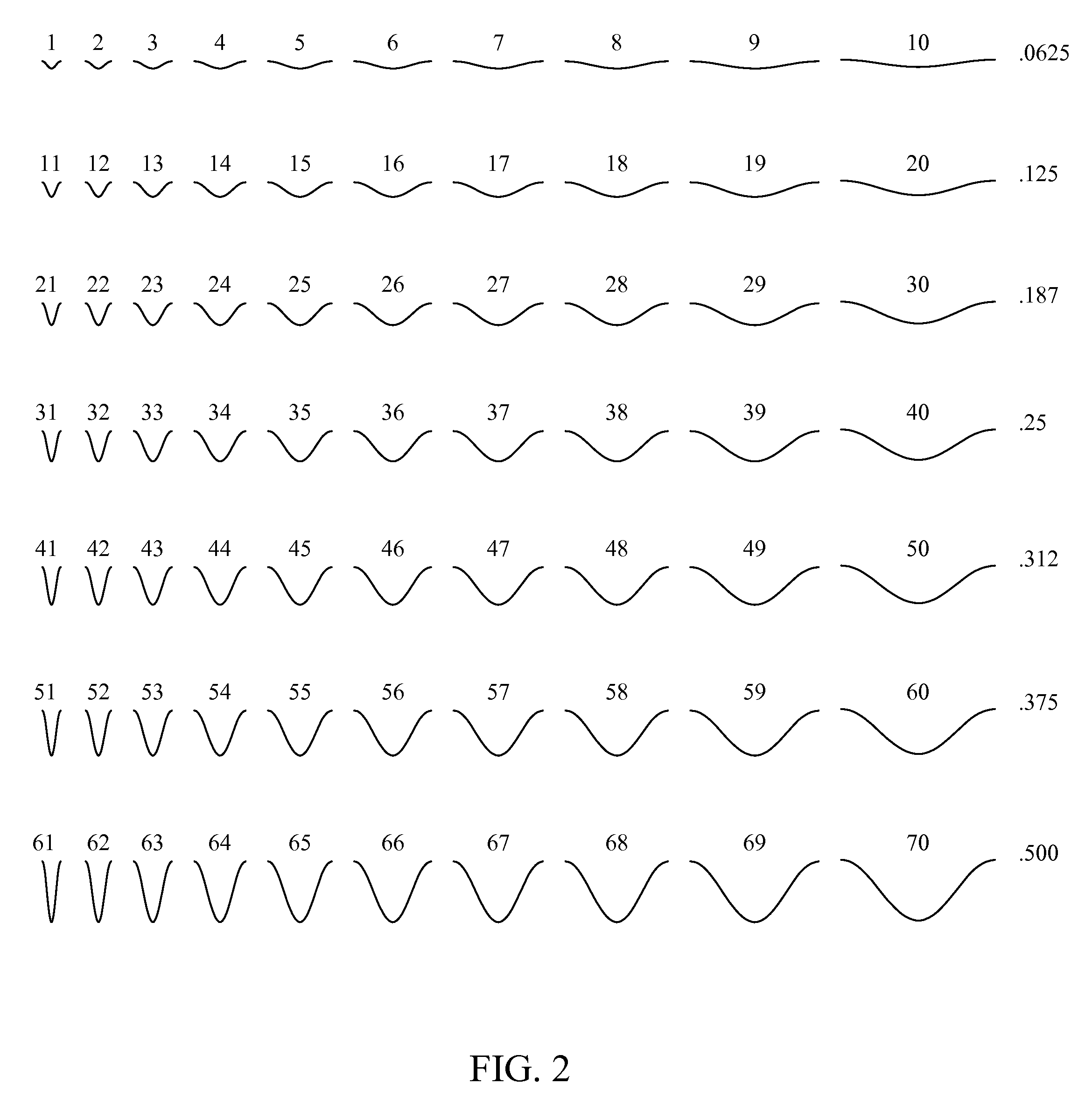
[0008]The embodiments disclosed herein for the present invention provide a coupon fabrication technique with defined distortion in the form of marceled fibers and test protocol to determine the shape of the failure probability density curve to improve the analyses of the risk of fiber distortion anomalies in composite structures. This protocol provides a method to determine the probability of and the severity of the various distorted fiber conditions that might exist on the rotor blades for the exemplary application in the future and those that are currently in fabrication and in service.
[0010]The determination of the failure characteristics instigated by distorted fibers in the material also enables improvements to the design of future composite structures. The data provided by the invention and associated finite element analyses which can be conducted based on the test protocol enhances engineering decision-making ability and add to the knowledge of composite materials engineering, stress engineering, quality engineering and composite testing and quality verifications.

Problems solved by technology

As an example, fiber distortions occur in helicopter rotor blade spar straps near critical root end stations.
Any degradation of strength in that area is of concern.
However, since no repair is possible upon detection of distorted fibers in the root end as in many other critical structural components in aircraft and helicopters, the disposition can only be “use as is” or “scrap” depending on the severity of the distorted fibered composite.
No current models for glass reinforced composite materials are available.

Method used


Image

  • Method and apparatus for failure probability density function determination
  • Method and apparatus for failure probability density function determination
  • Method and apparatus for failure probability density function determination

Examples


Embodiment Construction

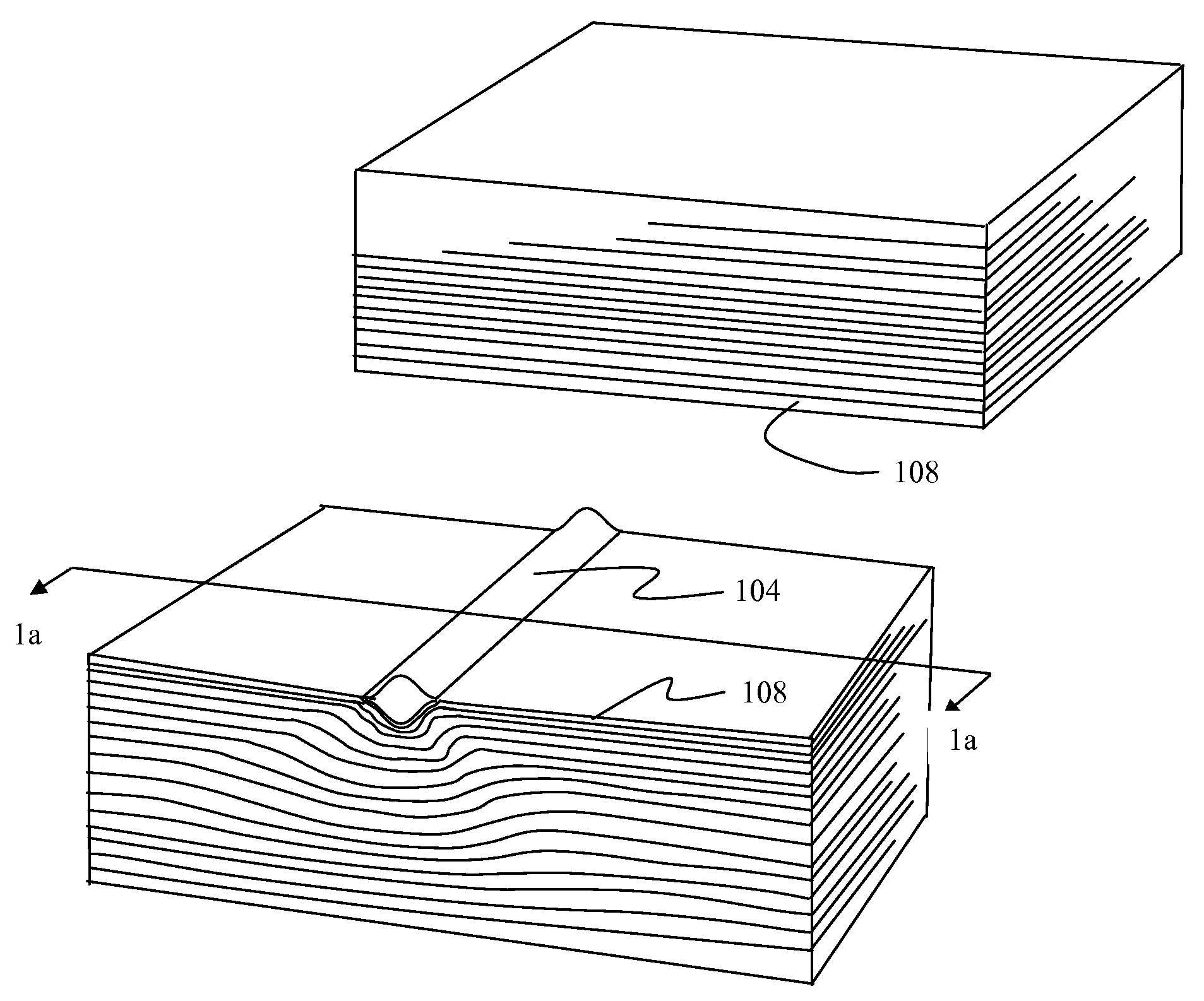
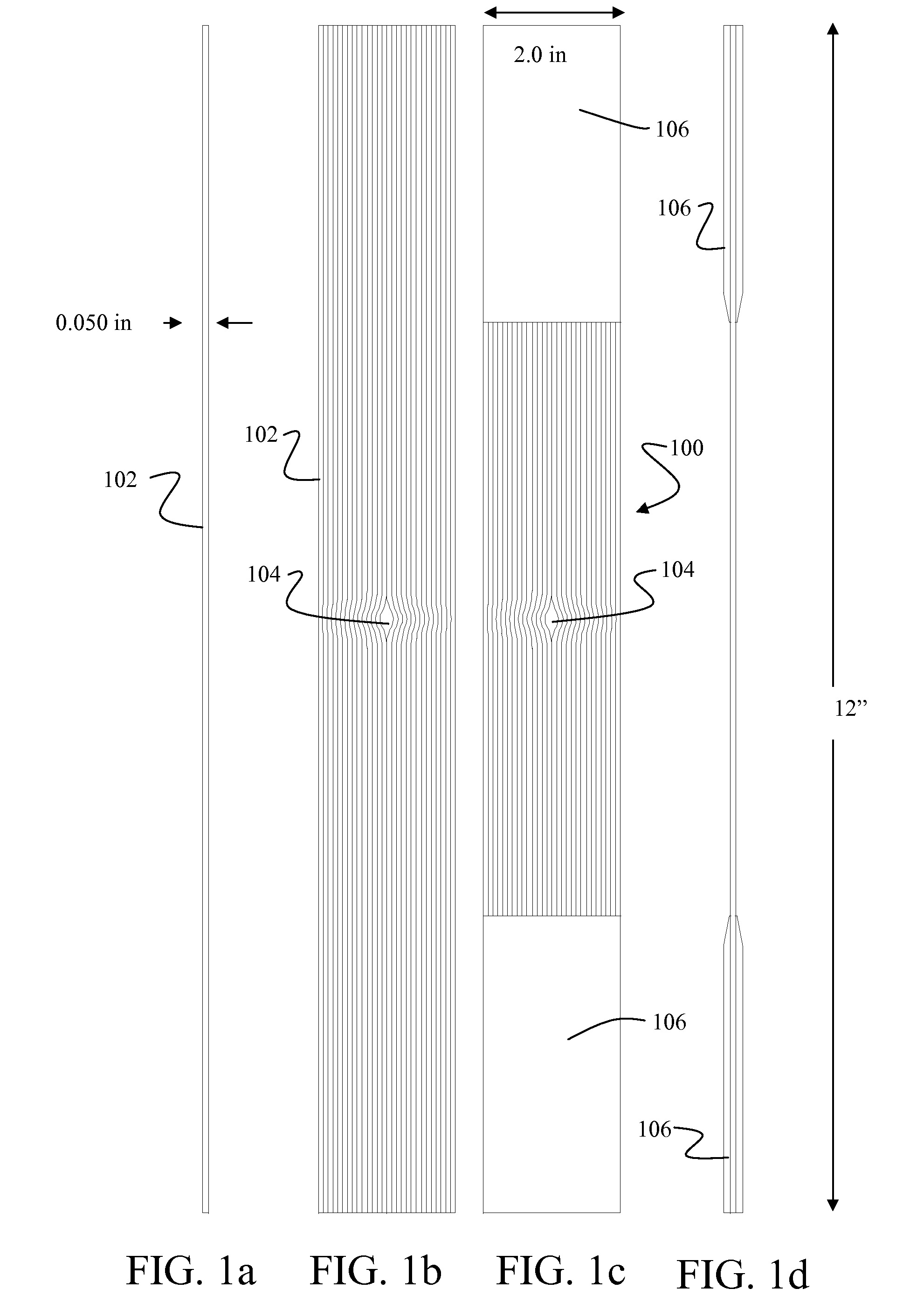
[0021]The protocol of the present invention defines the impact of fiber distortion defects on the tensile strength property of composite lay-ups. A coupon 100, shown in FIG. 1c employs the same materials and simulates the wave-like characteristics found in marceled distortions present in production fiber composite layups. For an exemplary composite system of BMS 08-196 Unidirectional coupons are built using a multi-ply layup incorporating a resign pool distortion shape selected from a distortion curve set as will be described in greater detail subsequently. For example coupons described herein the layup comprises 40 layers. The coupons are then sliced perpendicular to the layup with a thickness of approximately 0.050 inch. Tapes of varying width are created depending on the number of layers with 1.5 inch to 2.0 inch tapes 102, shown in FIGS. 1a (exaggerated in the thickness dimension in the figure for clarity) and 1b showing a 0.050 slice of the test element resin pool distortion sh...


PUM

PropertyMeasurementUnit
Fractionaaaaaaaaaa
Fractionaaaaaaaaaa
Fractionaaaaaaaaaa

Abstract

A coupon fabrication with defined distortion in the form of marceled fibers and test protocol is employed to determine the shape of the failure probability density curve to improve the analyses of the risk of fiber distortion anomalies in composite structures. This protocol provides a method to determine the probability of and the severity of the various distorted fiber conditions that might exist on composite structure in fabrication and in service. A distortion characterization matrix is established for determining test shapes and providing defect characterization based on the results of tests on the selected shapes. Coupons for test are created using resin pool

Description

BACKGROUND OF THE INVENTION[0001]1. Field of the Invention[0002]This invention relates generally to the field of testing for failure criteria determination in composite matrices and more particularly to a protocol including a method for coupon fabrication and testing to determine failure characteristics in multi-ply composite systems with templates for distortion comparison and disposition.[0003]2. Description of the Related Art[0004]Composite fabrication aircraft and helicopter structural systems requires high reliability for safety of flight elements. Testing for various voids or distortions in the plies of composite materials such as glass reinforced fiber composites and related determinations of engineering quality dispositions for anomalies that are located requires repeatable techniques for development of a database for use in such review. As an example, fiber distortions occur in helicopter rotor blade spar straps near critical root end stations. This area is critical because...

Claims


Application Information

Patent Timeline
IPC IPC(8): G01N3/32B29C35/00
CPCB29C70/543
Inventor MLINAR, SHARYN E.CAWTHORNE, MATTHEW H.DOWNEY, DAVID L.IRBY, DONNA M.
Owner THE BOEING CO
Learn More