
Orthopedic compression screw

a technology of orthopedic compression and screw, applied in the field of orthopedic compression screw, can solve problems such as problems posed by conventional techniques, and achieve the effect of simple and elegant manner

Inactive Publication Date: 2008-06-05
NORMED MEDIZIN TECHN VERTRIEBS
View PDF10 Cites 51 Cited by
  • Summary
  • Abstract
  • Description
  • Claims
  • Application Information

AI Technical Summary

Benefits of technology

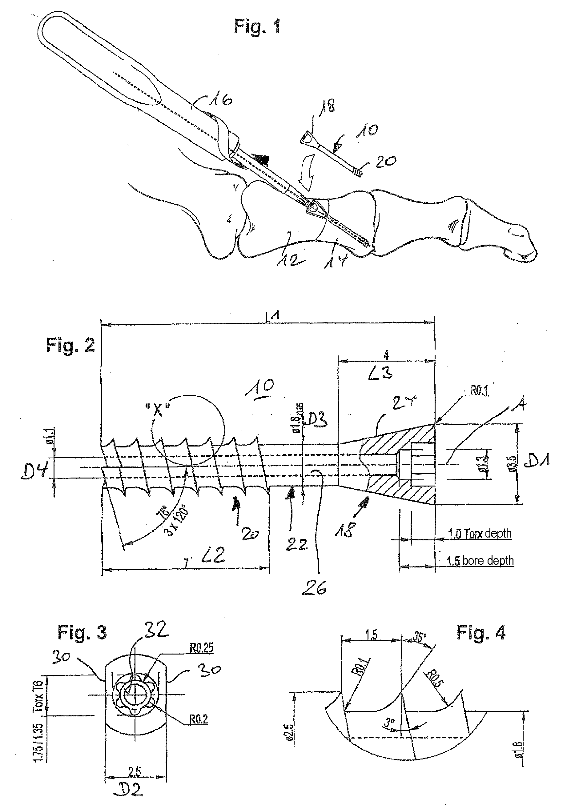
[0005]In an advantageous manner according to the invention, the periphery of the (partially) conically widened screw head of the orthopedic compression screw according to the invention is provided at least with one flat, preferably with two or more flats, such that, with minimal bone loss, the screws provided with a small head can be introduced very flat or obliquely (for example relative to a longitudinal axis of the bone), without the head disturbing the soft tissue parts at the operating site. Rather, the configuration claimed according to the invention allows the screw head to be embedded, such that the screws according to the invention are suitable especially for operating sites where there is a minimal covering of the bone by soft tissue. At the same time, the screw according to the invention allows the tensile force to be effectively introduced into or onto the bone via the cone shape of the head.
[0006]It is particularly preferable to define the geometry of the screw head (including the maximum distal diameter of the screw head, the angle inclination of the conical screw head jacket relative to the longitudinal axis of the screw, the groove depth of the thread or the diameter of the shaft portion, and the distance between the outer surfaces advantageously formed according to one development in a pair parallel to each other) in relative positions to one another, as in the dependent claims. In this way, it is possible to achieve in a particularly expedient manner the intended application purpose of osteosynthesis or bone fixation on sensitive bones of the extremities, in particular the bones of the feet, such that mechanical stability is advantageously balanced with ease of implantation and operation, a secure hold in the bone and optimized bone loss through insertion of the screw.
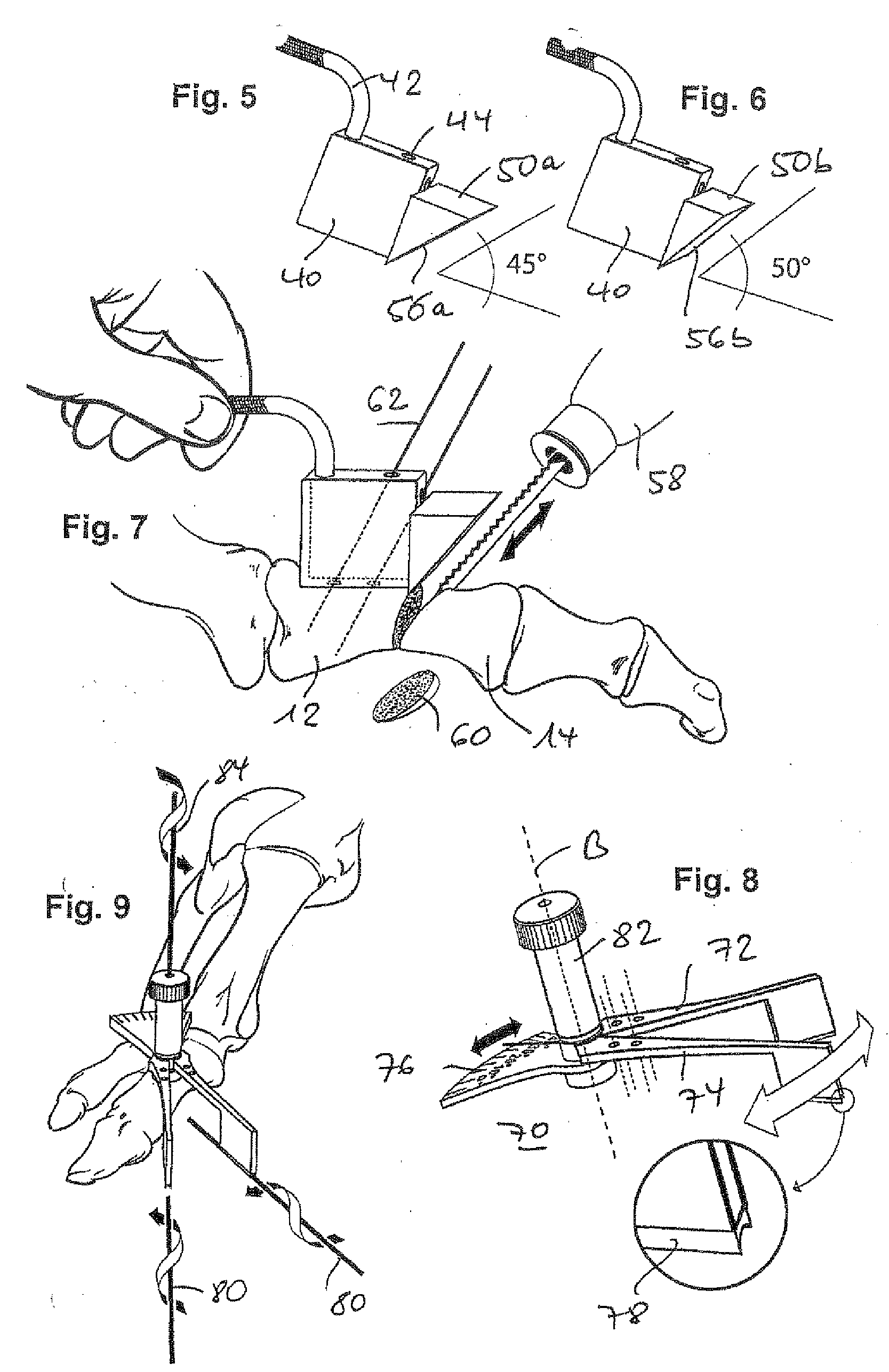
[0008]Independent protection in the context of the invention is claimed for a system for extracting a preferably wedge-shaped or disk-shaped bone segment from a bone, said system comprising an abutment or a guide surface for a cutting (sawing) procedure in the bone, and an orthopedic compression screw, in particular the compression screw according to the main claim, then permitting reconnection of the bone after extraction of the bone segment. According to the invention, the jig allows the cutting procedure for the extraction to be carried out in a constructively simple and surgically elegant and favorable manner, such that, according to the invention, the fixability of the jig on a guide element, in particular a guide wire (typically used: so-called Kirschner wire), is simplified and, in addition, the fixed angle adjustability of the jig designed, according to one development, as a modular multi-part assembly makes it particularly easy, at the operating site, to provide and orient the for example wedge-shaped extraction cut. In addition or alternatively, provision is advantageously made for the jig to be scissor-shaped and for the angles to be adjusted variably (preferably using a scale).
[0010]As a result, the technical medical problems described at the outset are solved by the present devices in a surprisingly simple and elegant manner; it is expected that, by virtue of the orthopedic compression screw according to the invention and its special geometry and by virtue of the extraction and fixation system according to the invention, the difficult area of foot (and hand) surgery may be enriched by fundamentally novel and advantageous technology.

Problems solved by technology

Conventional techniques present problems particularly when applied to surgery of so-called flexible hammer toes and in view of the resulting fixation requirements.
Deliberate shortening of the metatarsal bones in the metaphyseal and diaphyseal areas also represents an orthopedic challenge where, in addition to the problem of fixation by means of suitable screws, a further particular challenge lies in creating means with which a predetermined shortening of the bone can be permitted by predetermined bone cuts and removal in particular of disk-shaped and wedge-shaped bone segments.

Method used


Image

  • Orthopedic compression screw
  • Orthopedic compression screw
  • Orthopedic compression screw

Examples


Embodiment Construction

[0021]The geometries and geometrical relationships disclosed in the illustrative embodiments to be described below apply particularly as disclosed in relation to the invention, likewise the recognizable method steps.

[0022]Thus, FIG. 1 is a schematic representation showing how a compression screw 10 according to a first embodiment of the present invention is inserted (by means of a screwdriver 16 shown only by way of example) obliquely into a bone that has been divided into two halves 12, 14, such that a screw head 18 of the screw 10 can be inserted into the first bone part 12 in a manner substantially inclined relative to a longitudinal axis of the bone 12, 14, in such a way that the head 18 disappears completely in the bone substance, while a threaded portion 20 of the screw 10 sits in the adjacent bone part 14, with the result that the parts 12, 14 can be fixed onto each other by the action of the screw.

[0023]In the illustrative embodiment shown, not only does the detailed geometr...


PUM


Abstract

The invention relates to an orthopedic compression screw, in particular a compression screw for osteosynthesis and / or fixation of bone segments (12, 14), with a threaded portion (20) and a screw head (18), the screw head (18) widening conically toward its distal end and the screw being provided along its longitudinal axis (A) with a bore (26) for interaction with an orthopedic guide element, in particular a guide wire, and the periphery of the screw head (18) having at least one flat that forms a plane outer surface (30) preferably extending parallel to the longitudinal axis.

Description

BACKGROUND OF THE INVENTION[0001]The present invention relates to an orthopedic compression screw according to the preamble of the main claim. Devices of this kind are generally known from the prior art and are used particularly in orthopedic procedures carried out on the feet or hands. Screws of this kind, usually subjected to a tensile load when inserted, are used to fix bone parts to one another (again) in a desired connection position, so as to once more ensure the mechanical stability of the particular bone, which has been separated by a fracture or by a deliberate surgical measure.[0002]Conventional techniques present problems particularly when applied to surgery of so-called flexible hammer toes and in view of the resulting fixation requirements. Deliberate shortening of the metatarsal bones in the metaphyseal and diaphyseal areas also represents an orthopedic challenge where, in addition to the problem of fixation by means of suitable screws, a further particular challenge l...

Claims


Application Information

Patent Timeline
Patent Type & Authority Applications(United States)
IPC IPC(8): A61B17/56
CPCA61B17/152A61B2019/467A61B17/864A61B17/8605A61B2090/067
Inventor PECH, UWEWORNER, ROLANDVITEK, MICHAEL
Owner NORMED MEDIZIN TECHN VERTRIEBS
Learn More