
Semiconductor device and semiconductor package containing the same

Inactive Publication Date: 2008-05-29
LAPIS SEMICON CO LTD
View PDF5 Cites 5 Cited by
  • Summary
  • Abstract
  • Description
  • Claims
  • Application Information

AI Technical Summary

Benefits of technology

[0009]The present invention is developed to solve the above-described problem. In other words, an object of the present invention is to provide a semiconductor device and a semiconductor package for reducing the size of the semiconductor device without sacrificing the flatness of the passivation film, by utilizing the area under the bump electrode more effectively.
[0014]According to the present invention, an internal wiring can be arranged in an area where an electrode pad was conventionally formed, so that the chip size can be reduced. At the same time, the passivation film can be kept flat by certain formations of the internal wirings. Therefore, it is possible to prevent the manufacturing process from becoming complicated and the manufacturing cost from increasing, without providing a special design such as arranging dummy wirings under the bump electrode.
[0015]Because the passivation film is kept flat, the flatness of the bump electrode itself is improved, further improving the connection with the inner lead, which is connected with the bump electrode using a technology such as a thermal compression bonding process. Furthermore, it is possible to prevent a formation of a gap between the passivation film and the bump electrode, therefore, to reduce the risk of short circuit caused by a foreign substance getting into the gap.

Problems solved by technology

Recently, as the miniaturization of the semiconductor chip has progressed, the electrode pad has come to occupy a large portion of the chip footprint, leading to reduced competitiveness in cost.
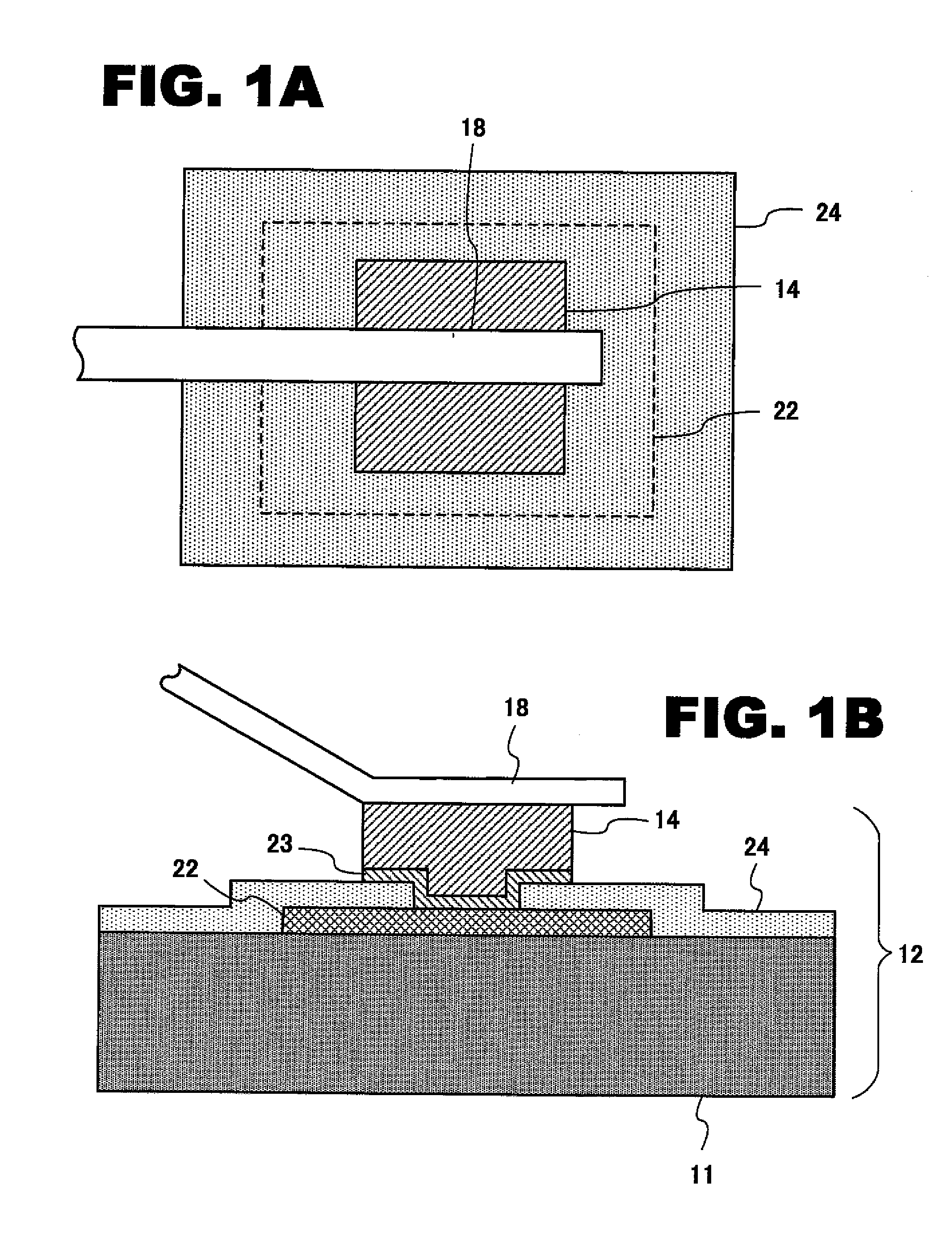
However, it has been difficult to reduce the size of the bump electrode itself while ensuring a sufficient area for contact thereof with the inner lead.
Thus, it has not been possible to utilize the area under the bump electrode 14, and, in turn, to reduce the size the semiconductor device itself.

Method used


Image

  • Semiconductor device and semiconductor package containing the same
  • Semiconductor device and semiconductor package containing the same
  • Semiconductor device and semiconductor package containing the same

Examples


Embodiment Construction

[0033]In the following detailed description of the preferred embodiments, reference is made to the accompanying drawings which form a part thereof, and in which is shown by way of illustration specifically preferred embodiments in which the inventions may be practiced. These preferred embodiments are described in sufficient detail to enable those skilled in the art to practice the invention, and it is to be understood that other changes may be made without departing from the spirit and scope of the present inventions. The following detailed description is, therefore, not to be taken in a limiting sense, and scope of the present invention is defined only by the appended claims.

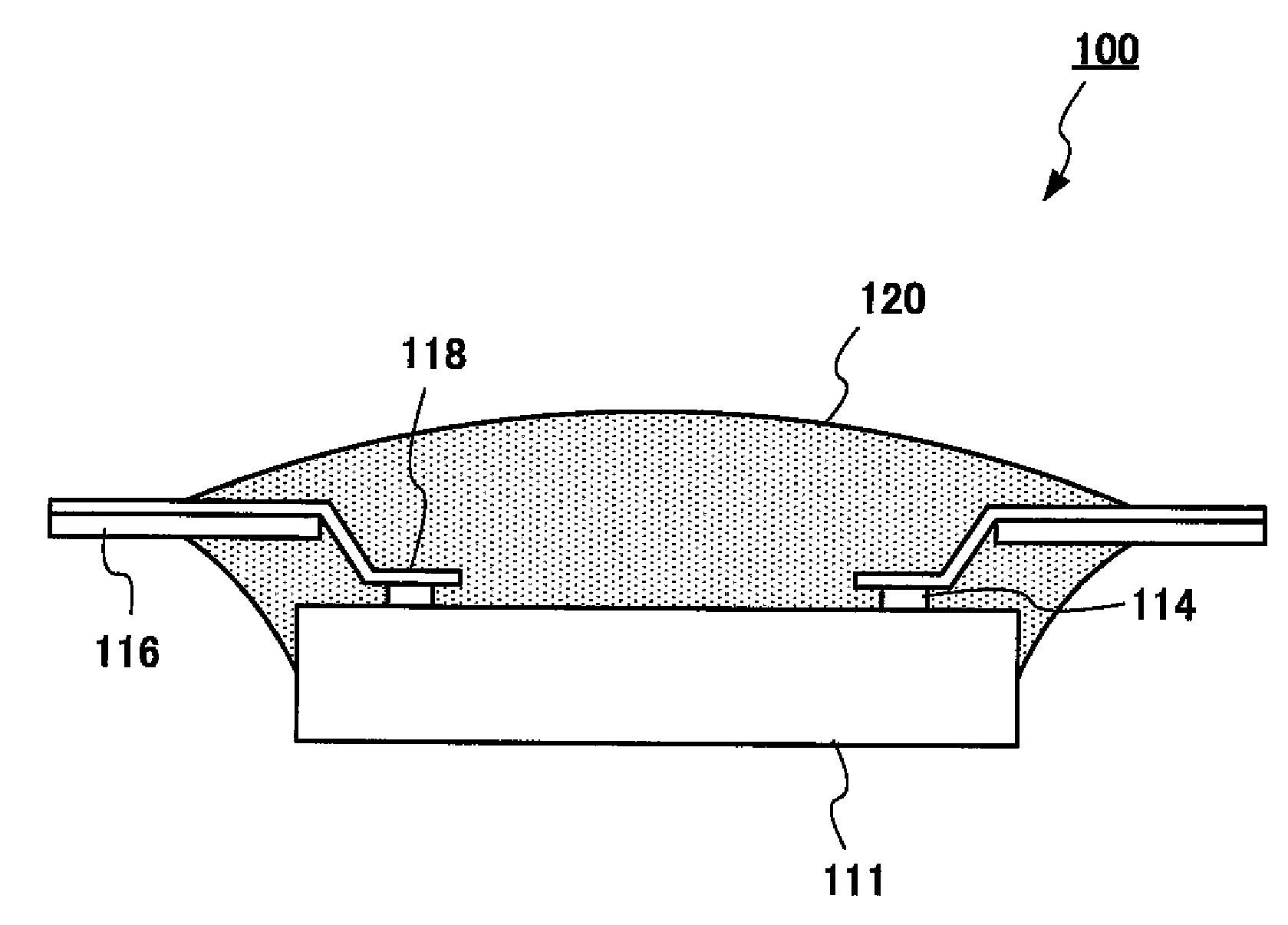
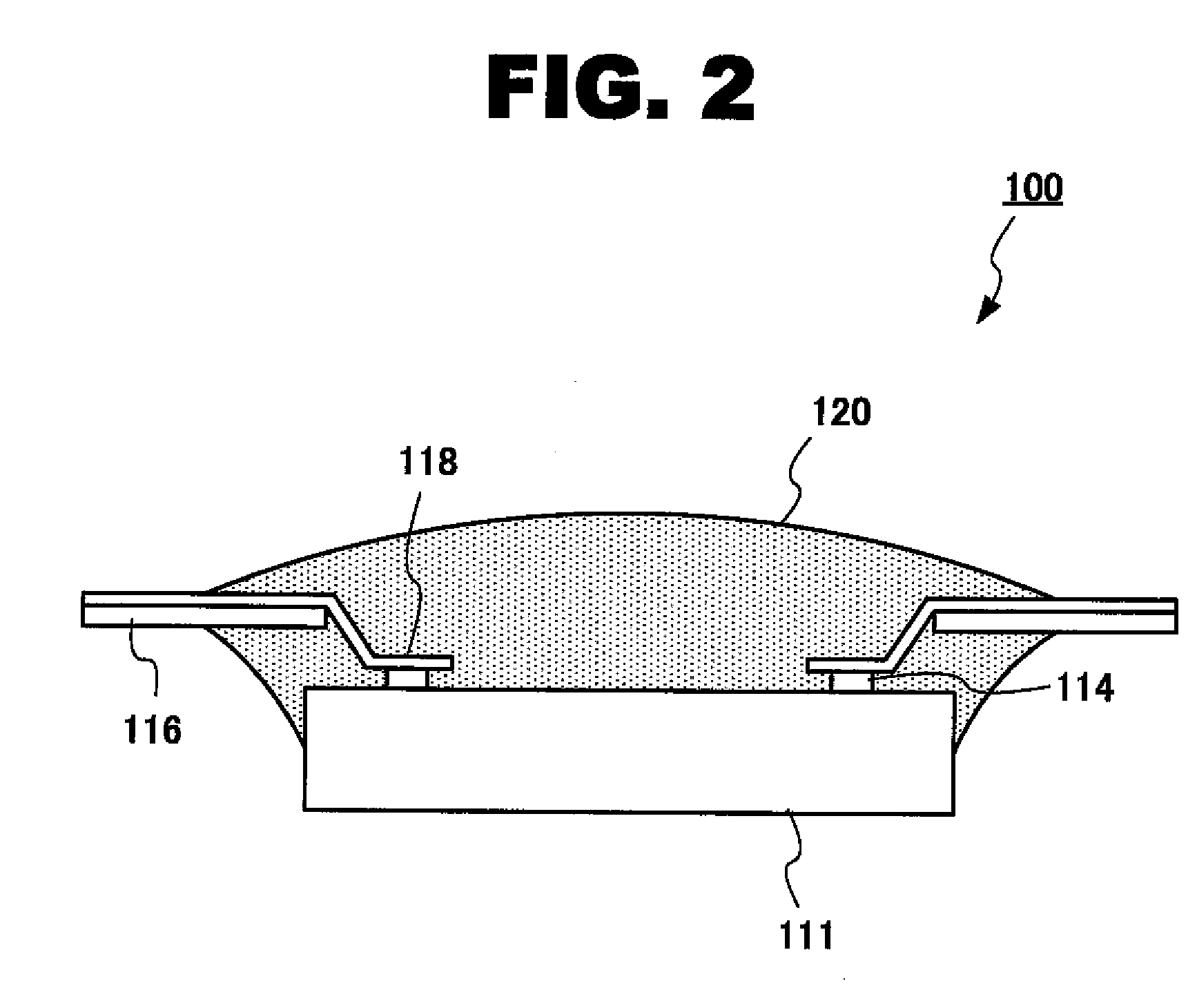
[0034]FIG. 2 is a side view of a semiconductor package related to the present invention. A semiconductor package 100 includes a semiconductor device 112, a plurality of leads 118, and a resin member 120. The semiconductor device 112 is provided with a semiconductor chip 111 and electrode pads 122. The semicondu...


PUM


Abstract

According to the present invention, a semiconductor device, having an electrode pad as a part of wirings on the uppermost layer thereof, includes a passivation film and a bump electrode for external connection. The passivation film is formed on the electrode pad, and the bump electrode is formed on the passivation film and electrically connected to the electrode pad. The electrode pad is formed so as to be smaller in size than the bump electrode, and a part of the wiring on the uppermost layer are formed under the bump electrode. In this manner, it is possible to utilize the area under the bump electrode effectively without sacrificing flatness of the passivation film. As a result, the semiconductor device and the semiconductor package can be made smaller.

Description

CROSS REFERENCE TO RELATED APPLICATION[0001]This application claims the priority of Application No. 2006-319417, filed Nov. 28, 2006 in Japan, the subject matter of which is incorporated herein by reference.TECHNICAL FIELD OF THE INVENTION[0002]The present invention relates to a semiconductor device having bump electrode as an external terminal, implemented with TCP (Tape Carrier Package) or COF (Chip On Film) technologies. More particularly, the present invention relates to an LCD (Liquid Crystal Display) driver package provided with a plurality of narrow-pitch bump electrodes.BACKGROUND OF THE INVENTION[0003]Upon assembling a product using the TCP implementation, a technology called TAB (Tape Automated Bonding) is used. On a main surface of a semiconductor chip, a bump electrode is formed as an external terminal, and the semiconductor chip is bonded to a film carrier with Inner-Lead Bonding (ILB). The film carrier has a long tape-like shape, on which repetitive wiring patterns are...

Claims


Application Information

Patent Timeline
IPC IPC(8): H01L23/48H01L23/28
CPCH01L23/3157H01L23/528H01L24/13H01L24/10H01L24/86H01L2224/13099H01L2924/01002H01L2924/01005H01L2924/01013H01L2924/01015H01L2924/01022H01L2924/01029H01L2924/01033H01L2924/01078H01L2924/01079H01L2924/01082H01L2924/14H01L2924/01006H01L2924/01047H01L2924/014H01L23/49811H01L2924/00H01L2224/13H01L2224/05022H01L2224/05001H01L2224/05572H01L2224/05124H01L2224/05147H01L2224/05644H01L2224/05655H01L2224/05666H01L2224/05669H01L2224/05684H01L24/81H01L24/50H01L24/05H01L2924/00014H01L2924/013H01L2924/01074H01L2924/01014
Inventor YAMAMOTO, HIROSHITAKEICHI, EIJI
Owner LAPIS SEMICON CO LTD
Learn More