
Film forming method, film forming apparatus and pattern forming method

a film forming and film technology, applied in the direction of photomechanical equipment, photosensitive materials, instruments, etc., to achieve the effect of preventing peeling on the surfa

Active Publication Date: 2008-05-22
TOKYO ELECTRON LTD
View PDF2 Cites 7 Cited by
  • Summary
  • Abstract
  • Description
  • Claims
  • Application Information

AI Technical Summary

Benefits of technology

[0007]The invention has been made in view of the above circumstances, and an object of the invention is to provide a film forming method and a film forming apparatus that can prevent peeling of a surface film including a resist film from a substrate during immersion exposure, to provide a pattern forming method including the above film forming method and to provide a computer-readable storage medium that stores a control program for executing the film forming method.
[0015]According to the invention, the surface film formed of the photoresist film or formed of the photoresist film and one or more kinds of films other than the photoresist film is formed on the substrate surface; and then the peripheral film is formed at least on the boundary portion including the periphery of the substrate and the periphery of the surface film. Therefore, the invention can prevent peeling of the surface film including the photoresist film from the substrate during the immersion exposure. Therefore, it is possible to avoid contamination of an exposure device, and a development quality can be improved.

Problems solved by technology

When the film is peeled off, the peeled film changes into particles, which may contaminate an exposure device (e.g., the projection lens) and / or may cause a development defect.

Method used


Image

  • Film forming method, film forming apparatus and pattern forming method
  • Film forming method, film forming apparatus and pattern forming method
  • Film forming method, film forming apparatus and pattern forming method

Examples


Embodiment Construction

[0023]An embodiment of the invention will be described below with reference to the drawings.

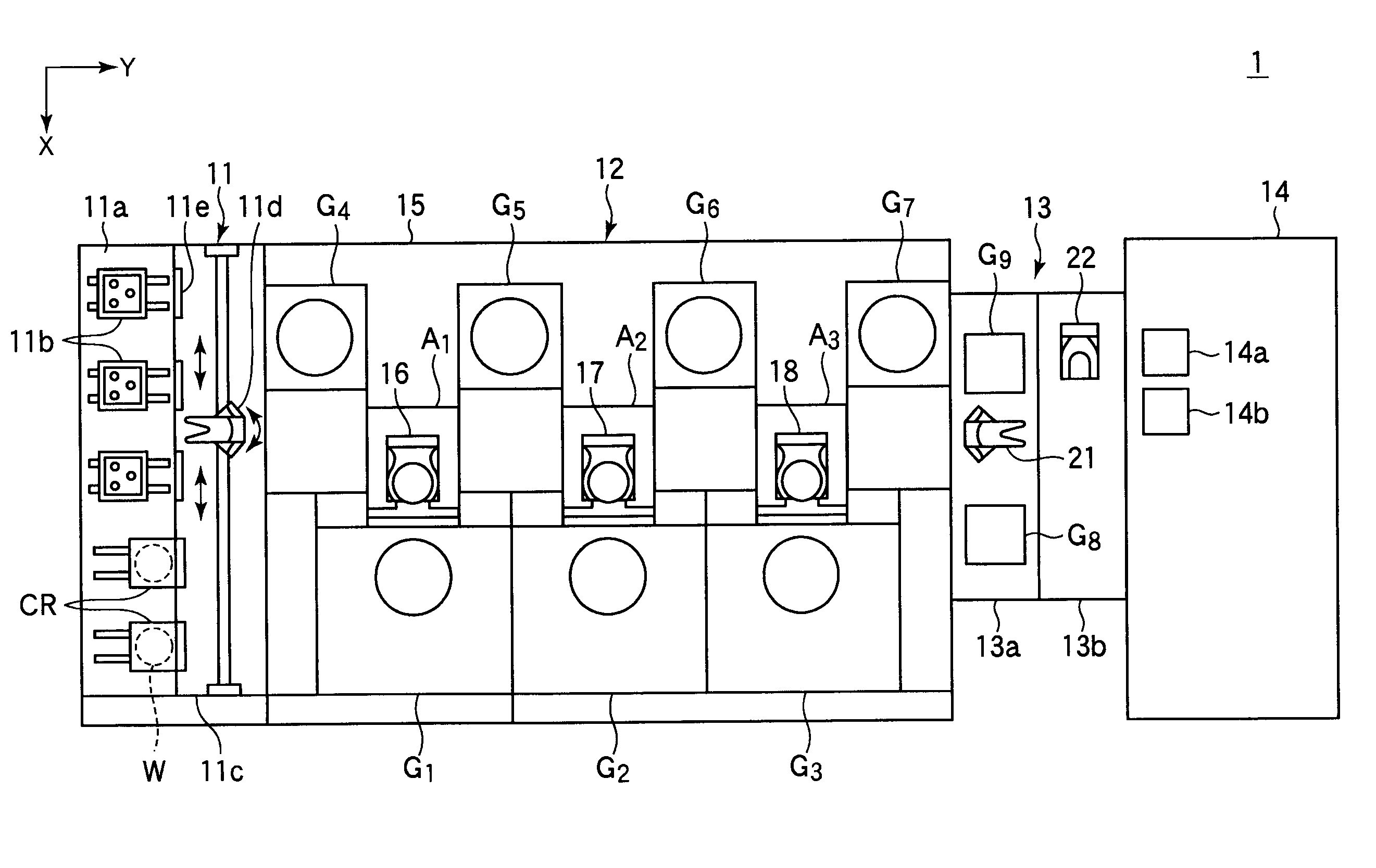
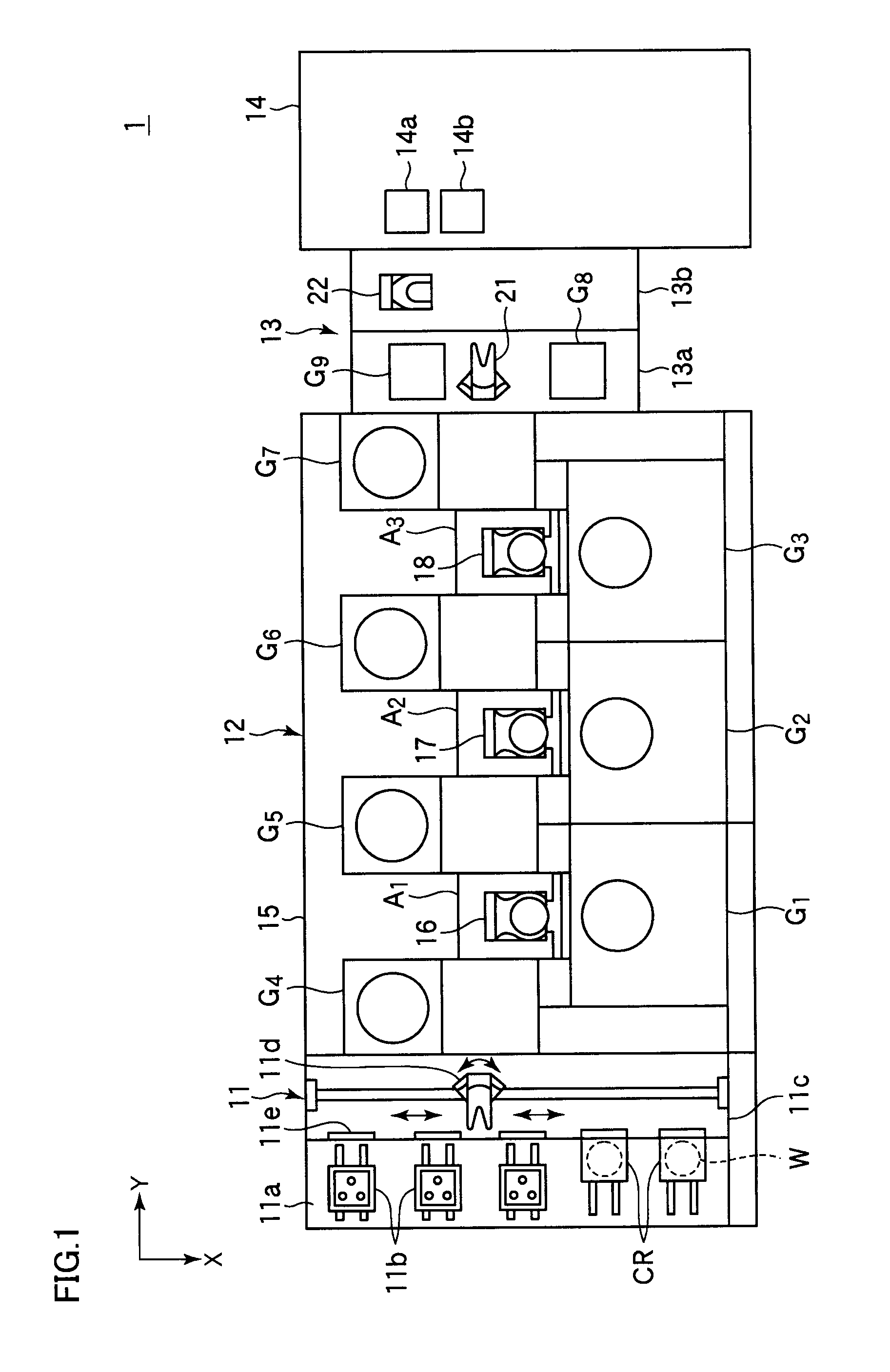
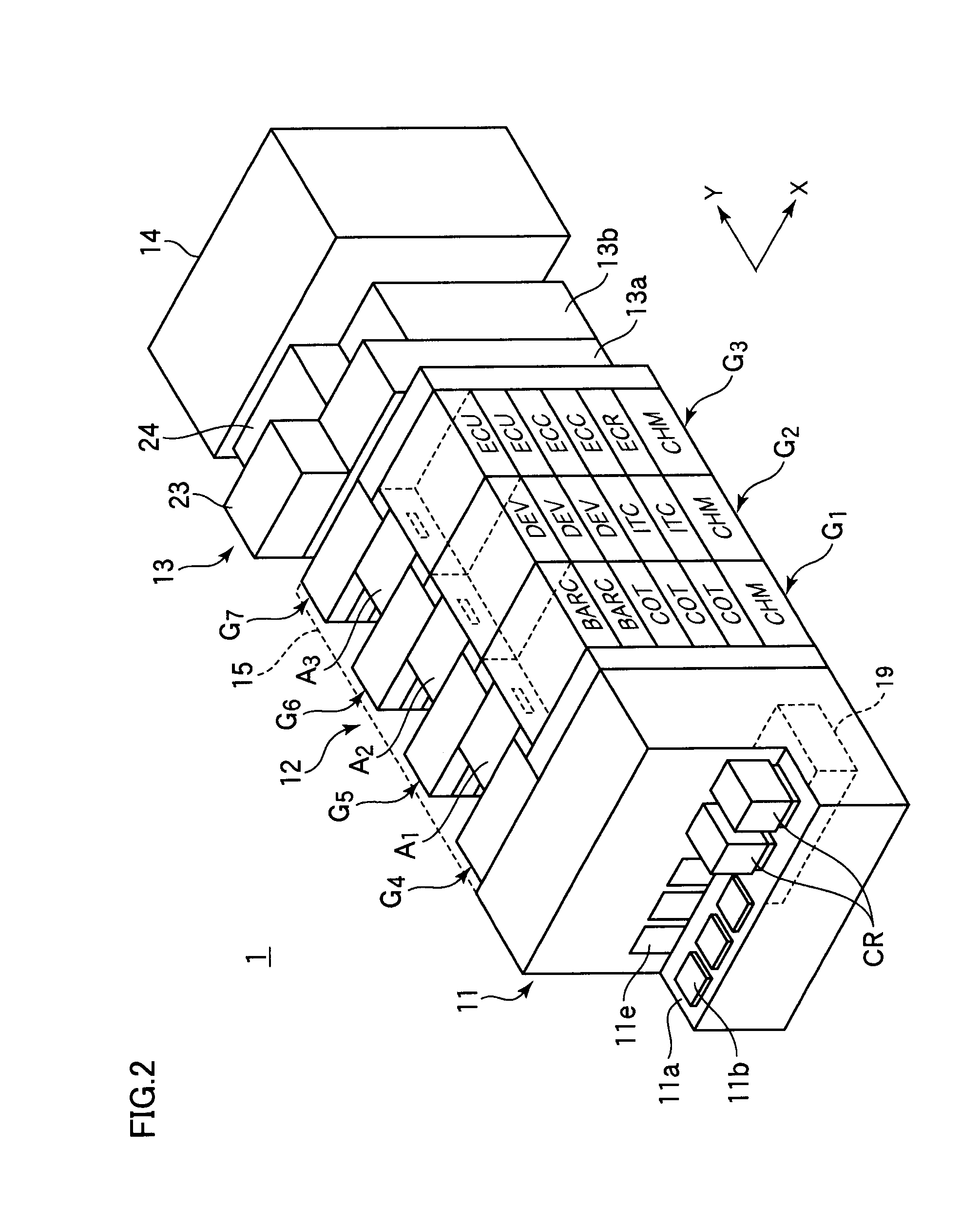
[0024]FIG. 1 is a schematic plan of a pattern forming apparatus that can execute a film forming method and a pattern forming method according to the invention, and FIG. 2 is a schematic perspective view thereof.

[0025]A pattern forming apparatus 1 is configured to form a predetermined resist pattern on a semiconductor substrate, i.e., a wafer W, and includes a cassette station 11 that is a transfer station of wafer W, a processing station 12 having a plurality of processing units that perform predetermined processing on wafer W after and before exposure processing, an exposure device 14 performing the exposure processing on wafer W and an interface station 13 for transmitting wafer W between processing station 12 and exposure device 14. Cassette station 11, processing station 12, interface station 13 and exposure device 14 are serially arranged in this order in a lengthwise direction (Y direct...


PUM

PropertyMeasurementUnit
temperatureaaaaaaaaaa
anti-reflectionaaaaaaaaaa
packaging densitiesaaaaaaaaaa

Abstract

Such a film forming method is provided that can prevent peeling of surface films including a resist film from a substrate during immersion exposure.The film forming method includes the steps of forming surface films including a resist film and a protective film covering the resist film over a surface of a wafer, and forming an edge cap film by supplying an edge cap film material to at least a boundary portion including a periphery of the wafer and peripheries of the surface films such as the protective film.

Description

BACKGROUND OF THE INVENTION[0001]1. Field of the Invention[0002]The present invention relates to a film forming method and a film forming apparatus by which a film used for immersion exposure processing of performing exposure processing through a liquid is formed on a substrate such as a semiconductor substrate, and also relates to a pattern forming method that includes the above film forming method and forms a predetermined resist pattern on a substrate.[0003]2. Description of the Background Art[0004]In a manufacturing process of semiconductor devices, a photolithography technique is used for forming a circuit pattern on a semiconductor wafer. When the photolithography is used, the circuit pattern is formed through steps of forming a resist film (photoresist film) by applying a resist liquid over a semiconductor wafer, irradiating the resist film with light to expose the resist film corresponding to the circuit pattern, and then developing it.[0005]Recently, there has been a tenden...

Claims


Application Information

Patent Timeline
Patent Type & Authority Applications(United States)
IPC IPC(8): G03C1/00
CPCG03F7/11G03F7/2041H01L21/6715H01L21/67115H01L21/6708
Inventor KOSUGI, HITOSHIYAMAMOTO, TAROYAMADA, YOSHIAKISAIGA, YASUHITO
Owner TOKYO ELECTRON LTD
Learn More