Construction machine

Active Publication Date: 2008-05-22
KOBELCO CONSTR MASCH CO LTD
View PDF83 Cites 4 Cited by
  • Summary
  • Abstract
  • Description
  • Claims
  • Application Information

AI Technical Summary

Benefits of technology

[0027]It is an object of the present invention to provide a construction machine capable of downsizing a working oil tank so as to ensure a sufficient working space for attaching and detaching a spool between the working oil tank and a control valve and also ensuring a necessary tank capacity under the condition that the control valve and the working oil tank are installed in line with each other and a part disturbed by a tank at the time of attachment and detachment thereof (a pressure compensating spool in the above example) is built in the control valve, or a construction machine provided with a working oil tank capable of avoiding direct contact of return oil with a side surface of a filter, separately connecting return tubes to a filter case and easing restrictions on a combination of the return tubes so as to simplify a connection structure.

Problems solved by technology

However by this, the return oil from lower tubes (particularly high pressure oil of a main tube) is brought into direct contact with a side surface of the filter and hence there is fear that the filtering surface (a filter paper) is damaged by pressure thereof.

Method used


Image

  • Construction machine
  • Construction machine
  • Construction machine

Examples


Embodiment Construction

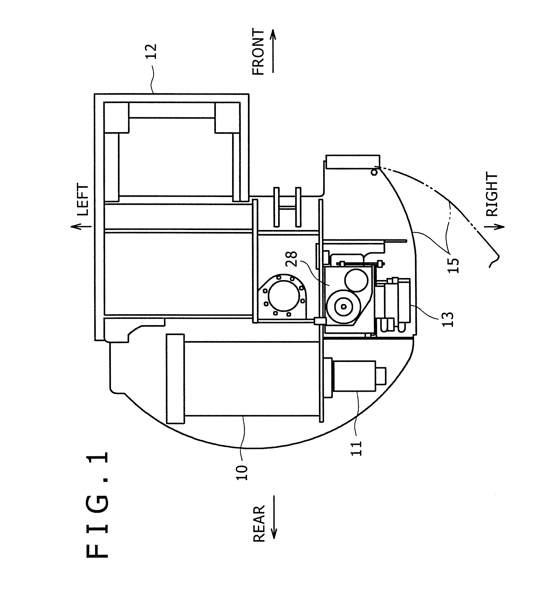
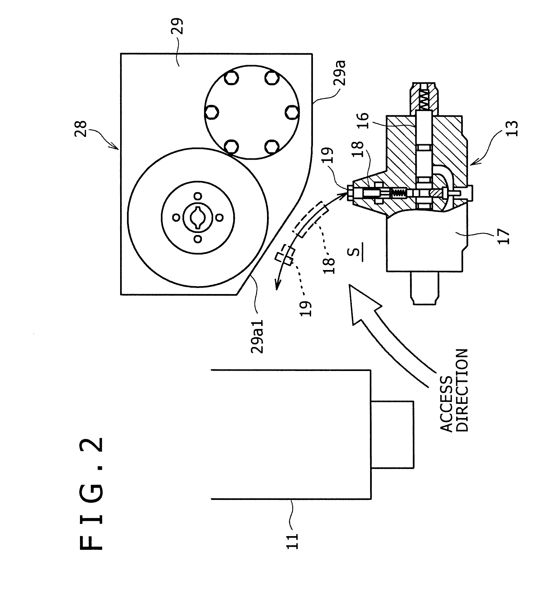
[0048]A description will be given to an embodiment of the present invention on the basis of FIGS. 1 to 4 and properly with reference to FIGS. 5 to 9 for comparative explanation or the like. In the embodiment, a hydraulic excavator is taken as an example of an object to which the present invention is applied.

[0049]FIGS. 1 and 2 show device arrangement of a part of an upper frame 12, and correspond to THE RELATED ART shown in FIGS. 6 and 7.

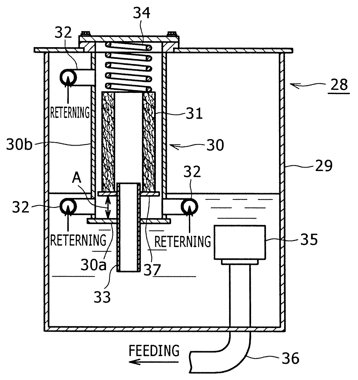
[0050]A basic configuration of the embodiment is as follows.[0051](i) In a rear part of the upper frame 12, are installed an engine 10 and a hydraulic pump 11. On the front side of the engine 10 and the hydraulic pump 11 on the right side, are laterally aligned a control valve 13 and a working oil tank 28.[0052](ii) In an end on the right side of the upper frame 12, is openably attached a guard cover 15 taking the front side as center. By opening the guard cover 15, maintenance of the control valve 13 and the working oil tank 28 is performed.[0053](...


PUM

PropertyMeasurementUnit
Speedaaaaaaaaaa
Shapeaaaaaaaaaa

Abstract

A rear half part of a surface of a main body of a working oil tank installed in line with a control valve opposing to the valve is dented in an inclining surface shape in the direction moving away from the valve so that between both the tank and the valve, is formed a working space for attaching and detaching a pressure compensating spool, while return tubes are separately connected to the upper and the lower side of a filter case side wall within the body. Within the body, is provided a cylindrical filter case having a bottom in which a return filter for return oil is housed, and the return tubes are connected to the case side wall in a state of communicating with the inside of the filter case. In this configuration, a filter receiving plate is provided in a lower part within the filter case with leaving a gap between the plate and the filter case bottom wall in a state that the plate is supported by a return pipe, the return filter is disposed on the plate, and the return tubes are connected to the filter case side wall on the lower side than the plate.

Description

BACKGROUND OF THE INVENTION[0001]1. Field of the Invention[0002]The present invention relates to a construction machine provided with a working oil tank such as a hydraulic excavator.[0003]2. Description of the Related Art[0004]THE RELATED ART will be described taking a hydraulic excavator of a preferred example of the present invention as an example.[0005]The hydraulic excavator is, as shown in FIG. 5, formed by rotatably mounting an upper rotating body 2 on a crawler type lower traveling body 1 and attaching a working attachment 3 to the upper rotating body 2.[0006]The working attachment 3 is formed by a boom 4 freely raising and lowering, an arm 5 attached to an front end of the boom 4, a bucket 6 attached to a front end of the arm 5, a boom cylinder 7, an arm cylinder 8 and a bucket cylinder 9 serving as hydraulic actuators for driving the boom, the arm and the bucket.[0007]FIG. 6 shows device arrangement of a part of the upper rotating body 2, and FIG. 7 is an enlarged view of ...

Claims


Application Information

Patent Timeline
IPC IPC(8): B60P9/00
CPCE02F3/325E02F9/0875F15B21/041F15B1/26E02F9/0883
Inventor MIYACHI, ISAO
Owner KOBELCO CONSTR MASCH CO LTD
Why Eureka
Try Eureka