
Physical quantity distribution detecting apparatus and imaging apparatus

a technology of physical quantity distribution and detecting apparatus, which is applied in the field of physical quantity distribution detecting apparatus and imaging apparatus, can solve problems such as noise generation, and achieve the effect of reducing the noise of circuits caused by potential variations in power supply or ground

Inactive Publication Date: 2008-05-15
SONY CORP
View PDF6 Cites 59 Cited by
  • Summary
  • Abstract
  • Description
  • Claims
  • Application Information

AI Technical Summary

Benefits of technology

[0016]It is desirable to provide a physical quantity distribution detecting apparatus that is capable of reducing circuit noise caused by a potential variation in a power supply or a ground and an imaging apparatus including a solid-state imaging device, which is the physical quantity distribution detecting apparatus, used as an imaging device.
[0019]As described above, even if the voltage drop occurs in the power-supply line, the comparison threshold of the comparator does not vary. Thus, circuit noise caused by the potential variation in the power-supply or the ground can be reduced.

Problems solved by technology

Thus, a large voltage drop occurs in the power-supply line L101 when a plurality of comparators are collectively inverted, resulting in generation of noise, which is problematic.

Method used


Image

  • Physical quantity distribution detecting apparatus and imaging apparatus
  • Physical quantity distribution detecting apparatus and imaging apparatus
  • Physical quantity distribution detecting apparatus and imaging apparatus

Examples


first embodiment

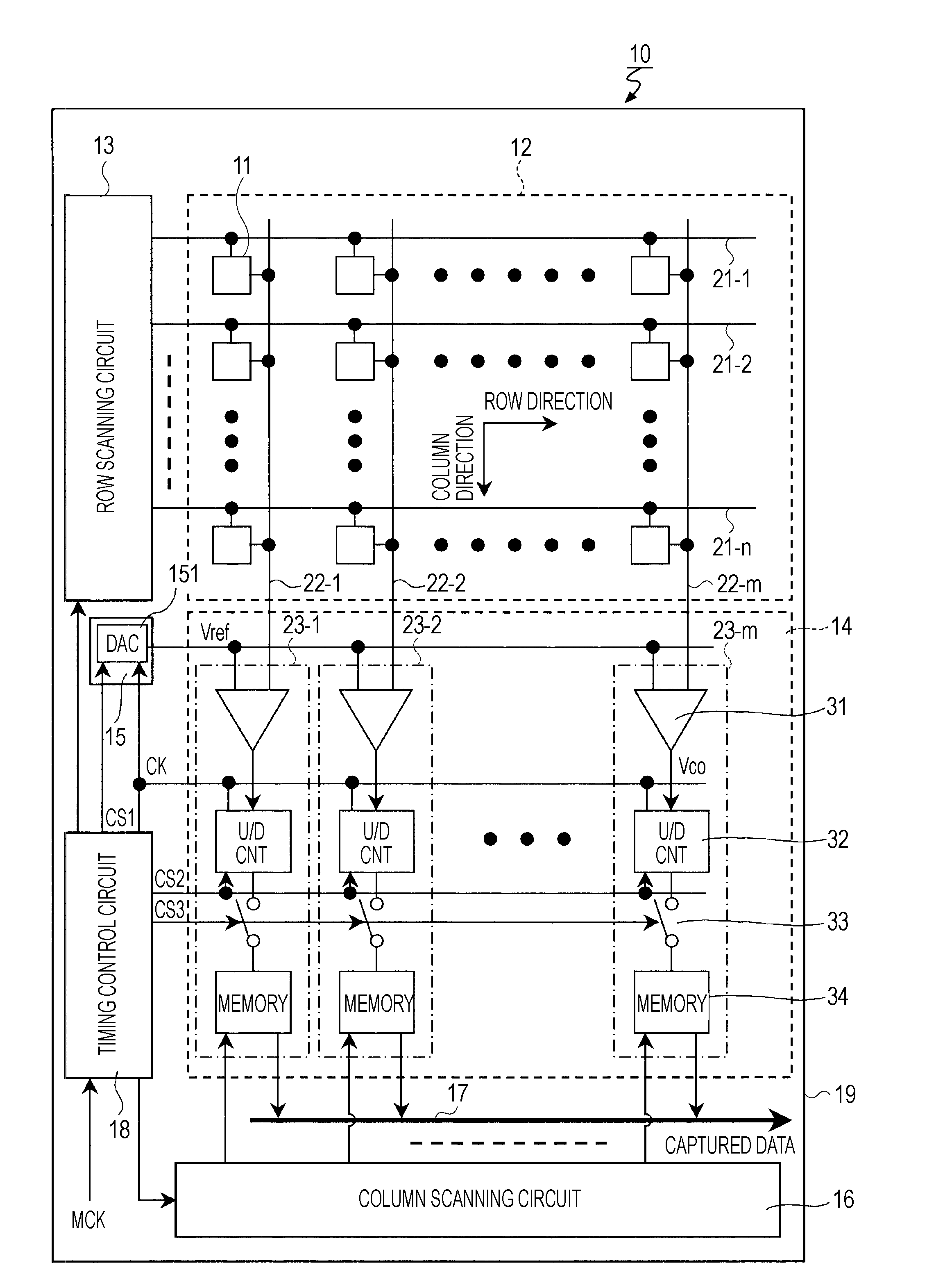
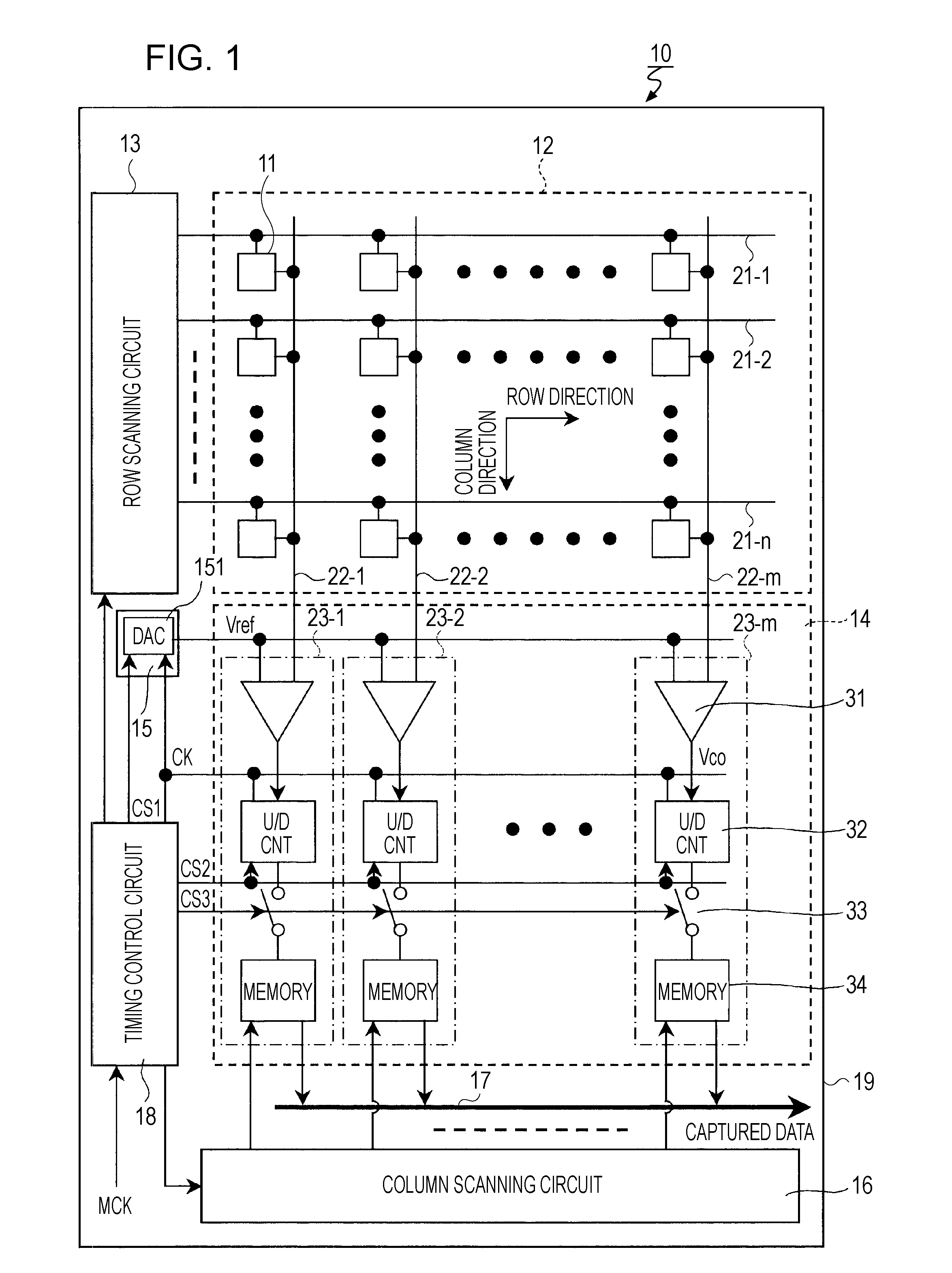
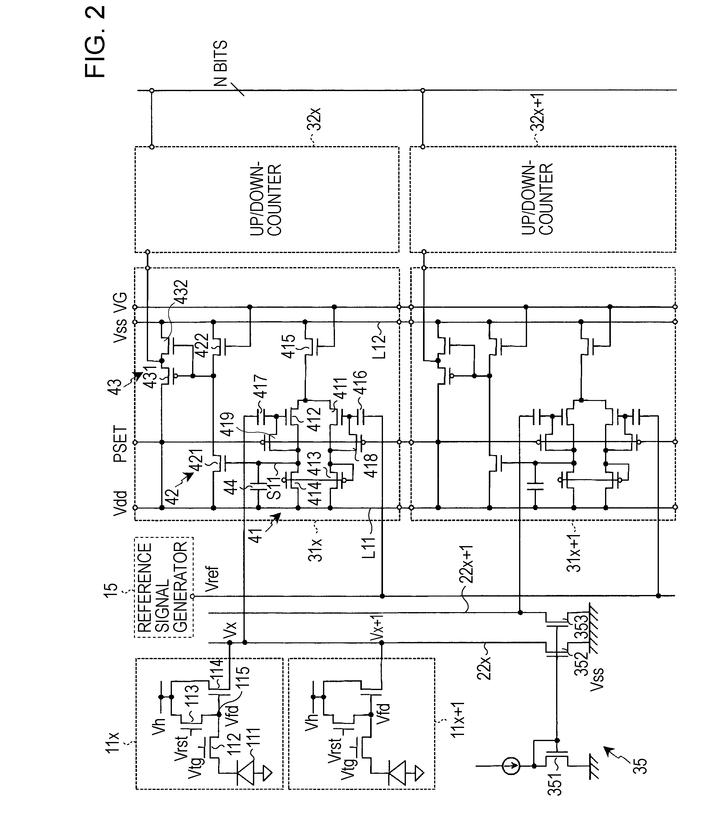
[0043]FIG. 2 is a circuit diagram showing an example of circuit configurations of comparators used in a first embodiment of the present invention. Specific circuit configurations of the comparators 31 (31x and 31x+1) in the xth column and the x+1th column will be described together with circuit configurations of the unit pixels 11 (11x and 11x+1). FIG. 3 shows an example of a circuit diagram in which a principal portion of FIG. 2 is enlarged.

[0044]Each of the unit pixels 11 includes a photoelectric transducer (for example, a photodiode) 111. Each of the unit pixels 11 also includes, for example, a transfer transistor 112 that transfers an electric charge obtained by photoelectric conversion at the photoelectric transducer 111 to a floating diffusion (FD) unit 115, a reset transistor 113 that controls the potential Vfd of the FD unit 115, and an amplifying transistor 114 that outputs a signal corresponding to the potential Vfd of the FD unit 115 to the corresponding column signal lin...

second embodiment

[0076]FIG. 5 is a circuit diagram showing an example of a circuit configuration of a comparator used in a second embodiment of the present invention. In FIG. 5, the same parts as in FIG. 2 are referred to with the same reference numerals.

[0077]Each of comparators 31A used in the second embodiment is similar to each of the comparators 31 used in the first embodiment with the exception of a configuration of a digital unit 43A. The differential input unit 41 and the inverted buffer unit 42 in the comparator 31A have the same configurations as the differential input unit 41 and the inverted buffer unit 42 in the comparator 31.

[0078]The digital unit 43A includes a CMOS inverter 433 and a CMOS inverter 436 that are cascaded together. The CMOS inverter 433 includes inverse-conductivity-type transistors 431 and 432 that are connected in series between the power-supply line L11 and the power-supply line L12. The gates of the inverse-conductivity-type transistors 431 and 432 are connected to ...


PUM


Abstract

A physical quantity distribution detecting apparatus includes a sensor array in which a plurality of unit sensors for sensing physical quantity are two-dimensionally arranged in a matrix; and an analog-to-digital conversion unit that includes a plurality of comparators for comparing an analog signal read from the unit sensor with a reference signal, the analog-to-digital conversion unit converting a digital signal by measuring a period of time or measuring a signal corresponding to the period of time of each comparison output of the plurality of comparators. Each of the plurality of comparators includes at least one capacitor element connected between a signal line and a constant-voltage line.

Description

CROSS REFERENCES TO RELATED APPLICATIONS[0001]The present invention contains subject matter related to Japanese Patent Application JP 2006-101387 filed in the Japanese Patent Office on Apr. 3, 2006, the entire contents of which are incorporated herein by reference.BACKGROUND OF THE INVENTION[0002]1. Field of the Invention[0003]The present invention relates to physical quantity distribution detecting apparatuses and imaging apparatuses, and more particularly, to a physical quantity distribution detecting apparatus including a column-parallel analog-to-digital (AD) conversion unit and an imaging apparatus including a solid-state imaging device, which is the physical quantity distribution detecting apparatus, used as an imaging device.[0004]2. Description of the Related Art[0005]As physical quantity distribution detecting apparatuses for sensing distribution of physical quantities, for example, solid-state imaging devices are available in which a plurality of unit pixels (unit sensors)...

Claims


Application Information

Patent Timeline
IPC IPC(8): H04N5/335H01L27/146H04N5/357H04N5/369H04N5/374H04N5/376H04N5/378
CPCH04N5/3742H04N5/357H04N25/60H04N25/767H04N25/78H04N25/76H04N25/618
Inventor TOYAMA, TAKAYUKIYASUI, YUKIHIROFUKUSHIMA, NORIYUKISUZUKI, ATSUSHI
Owner SONY CORP
Learn More