
Rotary motion mixer for a converging-stream nozzle of a turbomachine

Active Publication Date: 2008-05-08
SN DETUDE & DE CONSTR DE MOTEURS DAVIATION S N E C M A
View PDF6 Cites 17 Cited by
  • Summary
  • Abstract
  • Description
  • Claims
  • Application Information

AI Technical Summary

Benefits of technology

[0008]A main object of the present invention is thus to mitigate such drawbacks by proposing a daisy-petal type mixer that enables mixing between the cool stream and the hot stream to be improved so as to reduce the noise nuisance of the turbomachine.
[0010]By means of such a disposition of the radial walls of the inner lobes, the gas streams traveling along the inner gutters and those traveling along the outer gutters have rotary motion imparted thereto about the axis of symmetry of the cylindrical member at its outlet. Such rotary motion has the consequence of increasing the shear effects between the cool stream and the hot stream by adding an azimuth component to the mixing between these two streams. This encourages mixing between the cool stream and the hot stream, thereby improving the performance of the nozzle under cruising conditions.
[0011]From a noise point of view, adding this azimuth component to the mixing enables the jet noise at low frequencies to be diminished without thereby increasing noise levels at high frequencies.

Problems solved by technology

The sources of noise in a turbomachine are numerous, but that it has been found that the noise of the jet leaving the nozzle is the predominant noise during airplane takeoff.
Unfortunately, when the ejection conditions of the streams and the feeding of the bottoms of the lobes are not optimized, the magnitude of the turbulence generated by a daisy type mixer is not sufficient for obtaining really effective mixing between the cool stream and the hot stream, thus limiting the extent to which the jet noise levels can be reduced during airplane takeoff.

Method used


Image

  • Rotary motion mixer for a converging-stream nozzle of a turbomachine
  • Rotary motion mixer for a converging-stream nozzle of a turbomachine
  • Rotary motion mixer for a converging-stream nozzle of a turbomachine

Examples


Embodiment Construction

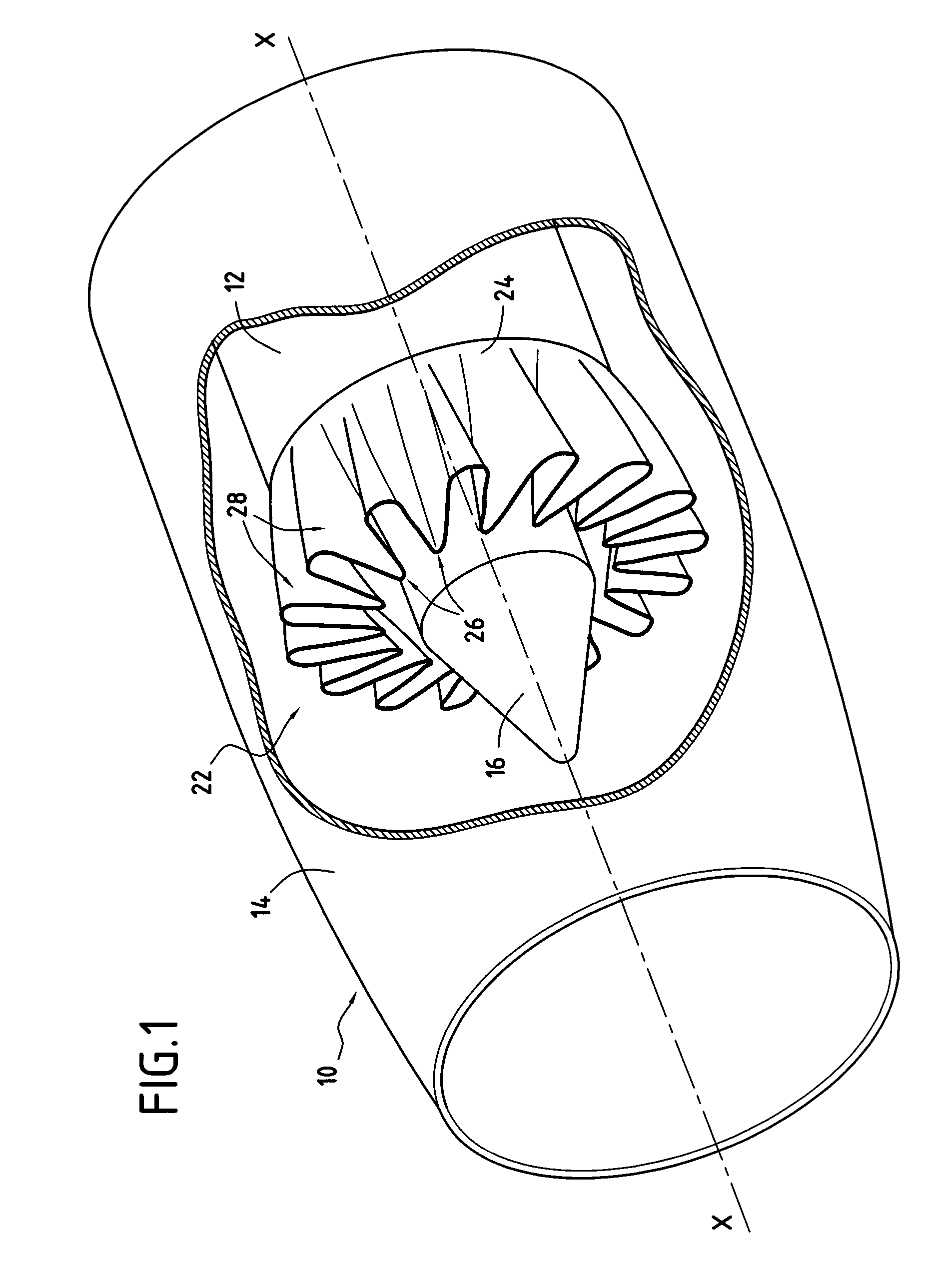
[0020]FIG. 1 is a cutaway diagrammatic perspective view of a nozzle 10 having converging streams in a bypass turbomachine.

[0021]The nozzle 10 is axially symmetrical in shape about its longitudinal axis X-X and is typically formed by a primary cover 12, a secondary cover 14, and a central body 16 all centered on the longitudinal axis X-X of the nozzle.

[0022]The primary cover 12 of substantially cylindrical shape extends along the longitudinal axis X-X of the nozzle. The central body 16 is disposed concentrically inside the primary cover and is terminated by a substantially conical portion.

[0023]The secondary cover 14, also substantially cylindrical in shape, surrounds the primary cover 12, being concentric thereabout and likewise extending along the longitudinal axis X-X of the nozzle. The secondary cover 14 extends longitudinally downstream beyond the primary cover 12.

[0024]It should be observed that in the embodiment shown in FIG. 1, the central body 16 of the nozzle 10 is of the e...


PUM


Abstract

The invention relates to a mixer for a bypass turbomachine, the mixer comprising a member having a sinusoidal portion at its end defining inner lobes and outer lobes, each outer lobe comprising a pair of plane radial walls spaced apart from each other in the circumferential direction and interconnected by an outer dome, each inner lobe comprising a pair of plane radial walls spaced apart from each other in the circumferential direction and connected together by an inner dome, the walls of the outer lobes being disposed to extend the walls of the inner lobes radially, the radial walls of a given outer lobe extending radially in mutually parallel directions, with these walls, when extended geometrically, defining a zone from which the axis of symmetry of the cylindrical member is excluded.

Description

BACKGROUND OF THE INVENTION[0001]The present invention relates to the general field of mixers for mixing concentric gas streams from a bypass turbomachine. The invention relates more particularly to a mixer of the daisy type for a converging-stream nozzle.[0002]Sound pollution is nowadays one of the major concerns of engine manufacturers who are receiving more and more objections to the sound nuisance of their turbomachines. The sources of noise in a turbomachine are numerous, but that it has been found that the noise of the jet leaving the nozzle is the predominant noise during airplane takeoff. Certification authorities are becoming more and more strict in terms of noise emission from turbomachines, and manufacturers have been requested to make efforts to reduce the noise that turbomachines generate, and in particular the jet noise at the outlet from the nozzle.[0003]Typically, a converging-stream nozzle of a turbomachine comprises a primary cover centered on the longitudinal axis...

Claims


Application Information

Patent Timeline
IPC IPC(8): F02K1/00F01N1/14F02K1/46
CPCF02K1/386F02K3/072F02K1/48
Inventor DUSSILLOLS, LAURENT CHRISTOPHEVUILLEMIN, ALEXANDRE ALFRED GASTON
Owner SN DETUDE & DE CONSTR DE MOTEURS DAVIATION S N E C M A
Learn More