
Microcomputer, program and on-vehicle electronic controller

a microcomputer and electronic controller technology, applied in the field of microcomputer operation, can solve the problems of electric power waste, operation waste, and electric power waste again accordingly, and achieve the effect of saving power and reducing power consumption

Inactive Publication Date: 2008-05-01
DENSO CORP
View PDF2 Cites 13 Cited by
  • Summary
  • Abstract
  • Description
  • Claims
  • Application Information

AI Technical Summary

Benefits of technology

[0015] The present invention has been made in consideration of the foregoing. It is therefore an object of the present invention to quickly put a microcomputer into a sleep mode when possible and prevent electric power from being wasted.
[0019] The microcomputer can go to the sleep mode immediately when all the application tasks go to sleep-ready states and the microcomputer is ready for the sleep mode. It is possible to solve the problem of wasted power in the prior art.
[0020] The notification process is preferably performed at the end of the application task since, for example, when the application task issuing the notification terminates, the sleep transition management means determines whether or not all the application tasks go to sleep-ready states. It is thus possible to reliably prevent a sleep mode from occurring during execution of the application task.
[0021] It should be noted that an exemplary method is further provided, which can be implemented on a computer, for example, through the execution of a computer program. The exemplary computer program, such as that embodied as instructions read from an article of manufacture including a computer readable medium, allows a computer to perform procedures associated with an exemplary method or function as the sleep transition management means and can be embodied in a microcomputer without using additional hardware.
[0022] The exemplary microcomputer is applicable to various embodiments including an on-vehicle electronic controller that is especially requested to reduce the power consumption. The microcomputer can further save the power when the on-vehicle electronic controller is capable of being inactivated.

Problems solved by technology

However, since the system task is still asleep, it will not check the flags until time t5 and place the microcomputer in the sleep mode at the end of the checking procedure.
Thus, as is shown in FIG. 7, the time between t4 and then end of t5 represents wasted operation and, accordingly, electric power is wasted.
However, use of the idle task to control transition to the sleep mode also causes problems similar to those associated with use of the system task for the following reasons.
In the present example however, operation is wasted between the time when the application task 1 terminates and the time when the application task 2 terminates and electric power is again accordingly wasted.
Thus, when the idle task is used to control transition to the sleep mode, transition out of the sleep mode may be difficult and it is further difficult to build other functions into the idle task.

Method used


Image

  • Microcomputer, program and on-vehicle electronic controller
  • Microcomputer, program and on-vehicle electronic controller
  • Microcomputer, program and on-vehicle electronic controller

Examples


Embodiment Construction

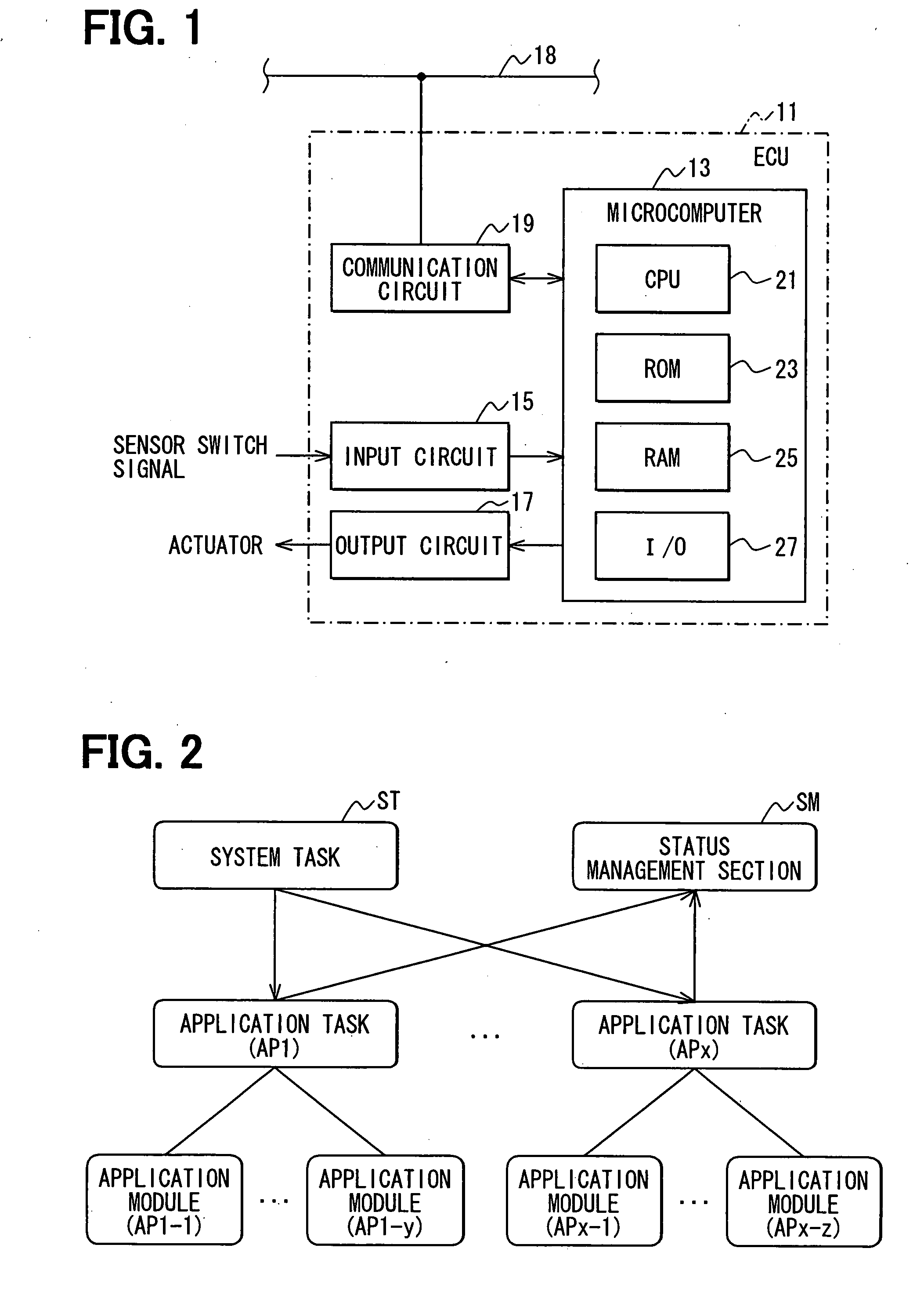
[0031] The following description of an on-vehicle electronic controller according to one or more exemplary embodiments of the invention is provided. The electronic controller according to the described embodiment or embodiments controls functions associated with vehicle body units such as a power window and a door lock. In the following description, it should be noted that the abbreviation “ECU” can refer herein to an electronic controller, electronic control unit, engine control unit, engine management unit, or the like as would be appreciated by one of skill in the art.

[0032] As shown in FIG. 1, an ECU 11 according to the present embodiment includes: a microcomputer 13; an input circuit 15, for example, that allows the microcomputer 13 to receive a sensor signal or a switch signal supplied from a circuit; an output circuit 17, for example, that outputs a drive signal to various actuators associated with, for example, a vehicle body assembly such as a power window motor and a door...


PUM


Abstract

A microcomputer is put into a sleep mode immediately when tasks become ready for the sleep mode so as to eliminate wasted power. Multiple application tasks are executed. Each application task provides notification regarding entry into sleep-ready state. When any application task provides notification, a status management section program sets a flag indicating that the application task goes to the sleep-ready state. The status management section checks flags of all the application tasks to determine whether all the application tasks go to the sleep-ready state, whereupon the microcomputer is put into the sleep mode.

Description

CROSS REFERENCE TO RELATED APPLICATIONS [0001] The present invention is related to and claims priority from unpublished Japanese Patent Application No. 2006-286330 the contents of which are incorporated herein by reference. BACKGROUND OF THE INVENTION [0002] 1. Field of the Invention [0003] The present invention relates to the operation of microcomputers. More specifically, the present invention relates to placing a microcomputer in a sleep mode. [0004] 2. Description of the Related Art [0005] Conventionally, a microcomputer used in an on-vehicle electronic controller uses a multitasking feature supplied from an operating system (OS) in order to execute multiple application tasks for controlling objects. [0006] When no process is needed, such microcomputer enables sleep mode that consumes less power than a normal operation (see e.g., Japanese Patent Application Laid-open No. JP-2005-182223 A). For example, the sleep mode decreases a CPU clock frequency or a power supply voltage, or ...

Claims


Application Information

Patent Timeline
IPC IPC(8): G06F1/32
CPCG06F1/3228G06F9/06G06F9/46G06F1/32
Inventor YOKOYAMA, KOUICHIROUNITTA, SHUICHISENOO, SHINICHIHIROTA, MASAYASASAKI, AKIHIRO
Owner DENSO CORP
Learn More