System and method for testing leds on a motherboard

a technology of leds and motherboards, applied in the field of system and method for testing leds on motherboards, can solve problems such as increased complexity, manual testing may likely destroy the pcb, and problems such as led production lines

Inactive Publication Date: 2008-05-01
HON HAI PRECISION IND CO LTD
View PDF11 Cites 11 Cited by
  • Summary
  • Abstract
  • Description
  • Claims
  • Application Information

AI Technical Summary

Benefits of technology

[0007]A system for testing light-emitting diodes (LEDs) on a motherboard includes: a motherboard, an insulating plate, a circuit board and a computer. The insulating plate covers the motherboard, and is configured with optical fibers to induce beams sourced from the LEDs and to transmit beams to a circuit board. The circuit board is connected to the insulating plate by the optical fibers. The circuit board includes at least one photoresistor configured for sensing the beams sourced from the LEDs to obtain influence values and for transmitting the influence values to a computer. The computer is configured for controlling the LEDs, to power on or power off, by controlling luminous intensities of the LEDs. This computer configuration is useful for detecting whether the influence values are within a photosensitive range when the LEDs are powered on. The computer is further configured for detecting whether resistance values of all and/or at least one photoresistor are equal to a dark resistance when the LEDs are powered off. The computer is also further configured for reporting test results.
[0008]A method for testing light-emitting diodes (LED

Problems solved by technology

However, in situations of manual testing, problems may occur in LED production lines.
First of all, manual testing may likely destroy the PCB, if the voltage passing through the PCB gets too high.
Secondly, the increase in complexity and the decrease in accuracy of LEDs may also lead to problems.
For example, if a human operator testing the characteristics of LE

Method used


Image

  • System and method for testing leds on a motherboard
  • System and method for testing leds on a motherboard
  • System and method for testing leds on a motherboard

Examples


Embodiment Construction

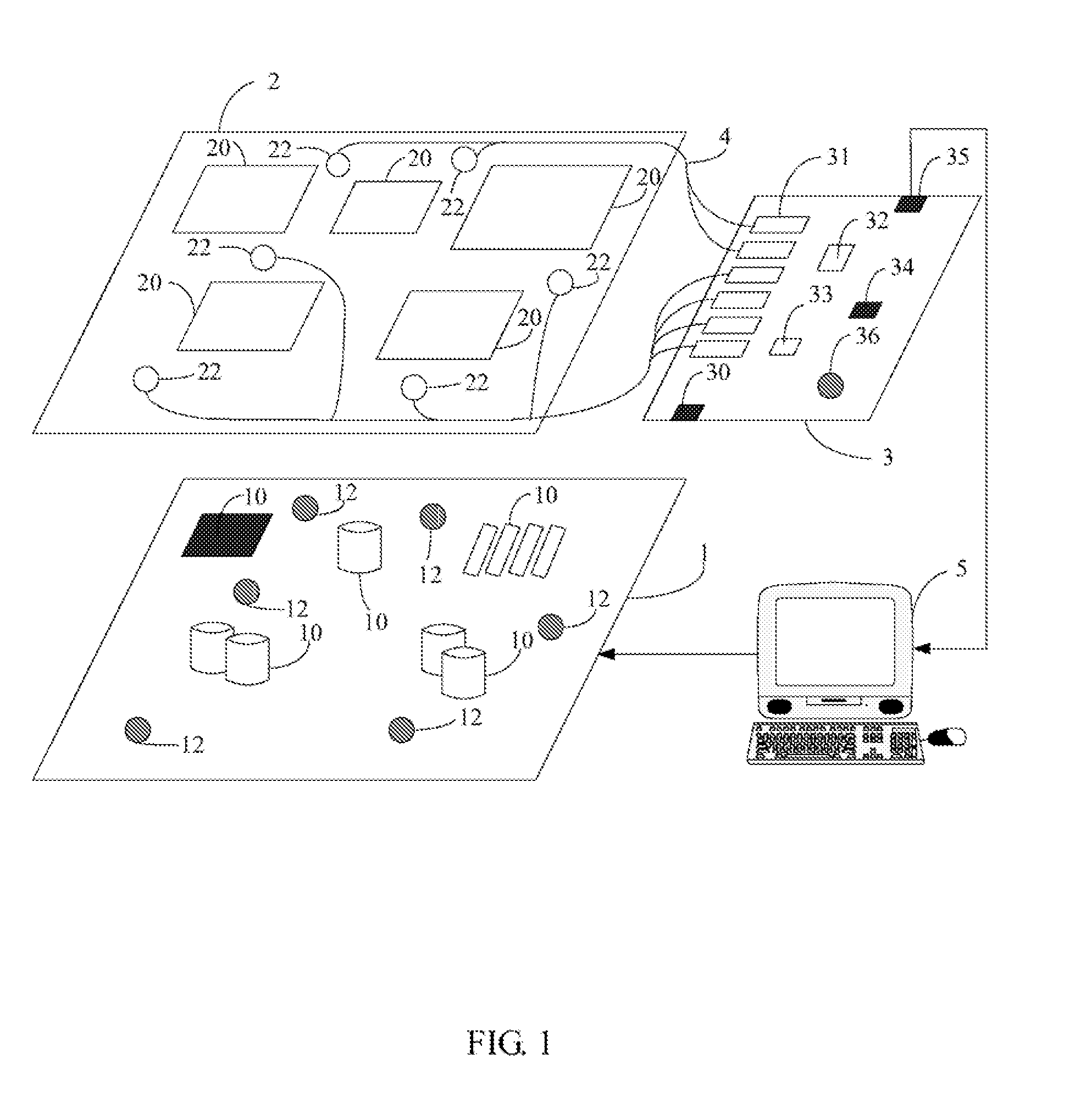
[0015]FIG. 1 is a schematic diagram of a system for testing light emitting diodes (LEDs) on a motherboard (hereinafter, “the system”) in accordance with one embodiment. The system typically includes: a motherboard 1, an insulating plate 2, a circuit board3, and a computer 5. The insulating plate 2 is positioned on the motherboard 1 and is overlaying with optical fibers 4. The optical fibers 4 in FIG. 1 are simply indicated, and the real size of each of the optical fibers 4 is neglected. Actually each of the optical fibers 4 is configured with a pipeline. The real size of each of the optical fibers 4 approximately equals the size of the LEDs. The insulating plate 2 is connected with the circuit board 3 via the optical fibers 4. In the preferred embodiment, the motherboard 1 can be incorporated into the computer 5. In an alternative embodiment, the motherboard 1 is external to the computer 5.

[0016]The motherboard 1 mainly includes multiple numbers of components 10 such as a CPU, resis...


PUM


Abstract

An exemplary system for testing light-emitting diodes (LEDs) on a motherboard is provided. The system typically includes: an insulating plate covered on the motherboard, configured with optical fibers for inducing beams sourced from the LEDs and transmitting the beams to a circuit board; the circuit board includes at least one photoresistor, configured for sensing the beams to obtain influence values; a computer configured for detecting whether the influence values are within a photosensitive range when the LEDs are powered on, for detecting whether resistance values of all the given number of at least one photoresistor are equal to a dark resistance when the LEDs are powered off and for reporting test results. A related method is also provided.

Description

BACKGROUND OF THE INVENTION[0001]1. Field of the Invention[0002]The present invention relates to the field of testing light emitting diodes (LEDs), and more particularly to a system and method for testing LEDs on a motherboard.[0003]2. Description of Related Art[0004]A light emitting diode (LED) have been applied with commercial products since the 1960s, due to its favorable characteristics. LEDs display high-shake endurance, long-service life, small power consumption and little heat production. As such, the LED can be applied for daily usage in a variety of ways, such as: household appliances, indicative illumination for equipments or as light sources. In recent years, a printed circuit board (PCB), such as a motherboard, has been made in such a way that it contains one or more LEDs. The one or more LEDs is / are used as external signals, internal diagnostics and for purposes of other suitable applications.[0005]In order to verify whether each LED located on the PCB works in a normal...

Claims


Application Information

Patent Timeline
IPC IPC(8): G01R31/26
CPCG01R31/2818G01R31/2635
Inventor WU, KUAN-LINCHEN, WEI-YUAN
Owner HON HAI PRECISION IND CO LTD
Why Eureka
Try Eureka