
Electrically Driven Compressor Integral with Inverter Device, and Vehicle Air Conditioner Where the Compressor is Used

Inactive Publication Date: 2008-04-24
PANASONIC CORP
View PDF19 Cites 13 Cited by
  • Summary
  • Abstract
  • Description
  • Claims
  • Application Information

AI Technical Summary

Benefits of technology

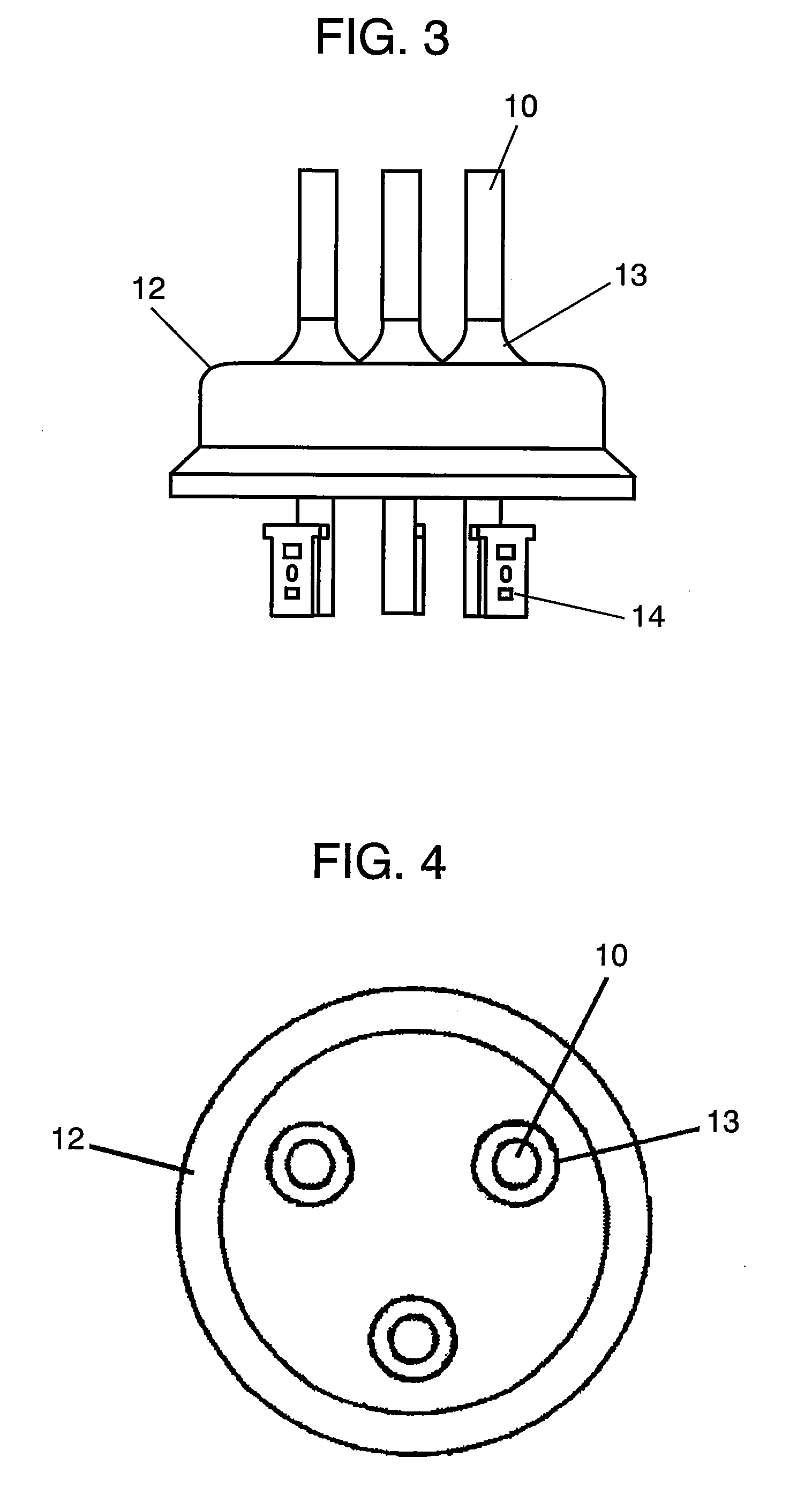
[0010]By virtue of the structure above, the soldered connection to the electric connection terminal can be easily and quickly obtained. This also allows an electrically driven compressor integrally formed with an inverter device to have a compact, lightweight structure and simple assembly work.

Problems solved by technology

The necessities above increase a parts count and an installation space, which is an obstacle to a compact and lightweight structure.
In addition, the assembly process increases due to increase in parts count.
On the other hand, a soldered connection has following problems.
Due to the large heat capacity of the alloys, the soldering work requires a heating device with large capacity.

Method used


Image

  • Electrically Driven Compressor Integral with Inverter Device, and Vehicle Air Conditioner Where the Compressor is Used
  • Electrically Driven Compressor Integral with Inverter Device, and Vehicle Air Conditioner Where the Compressor is Used
  • Electrically Driven Compressor Integral with Inverter Device, and Vehicle Air Conditioner Where the Compressor is Used

Examples


first exemplary embodiment

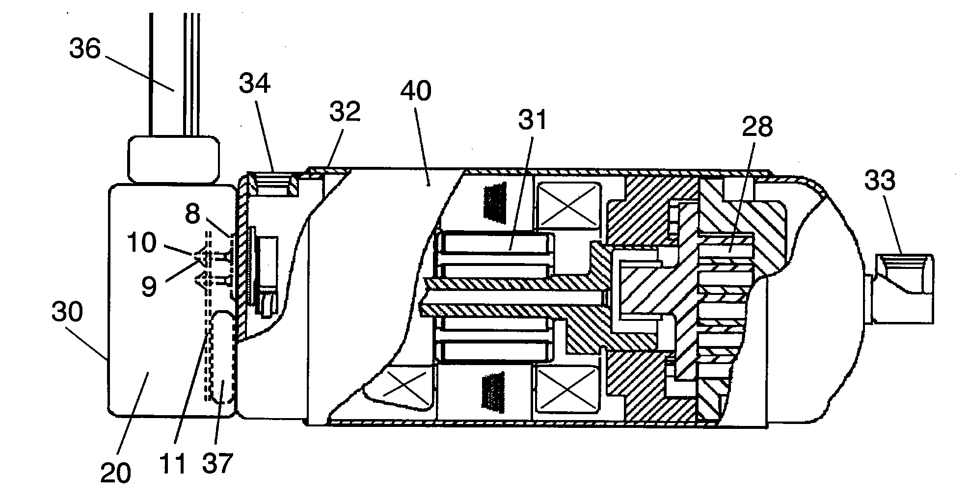
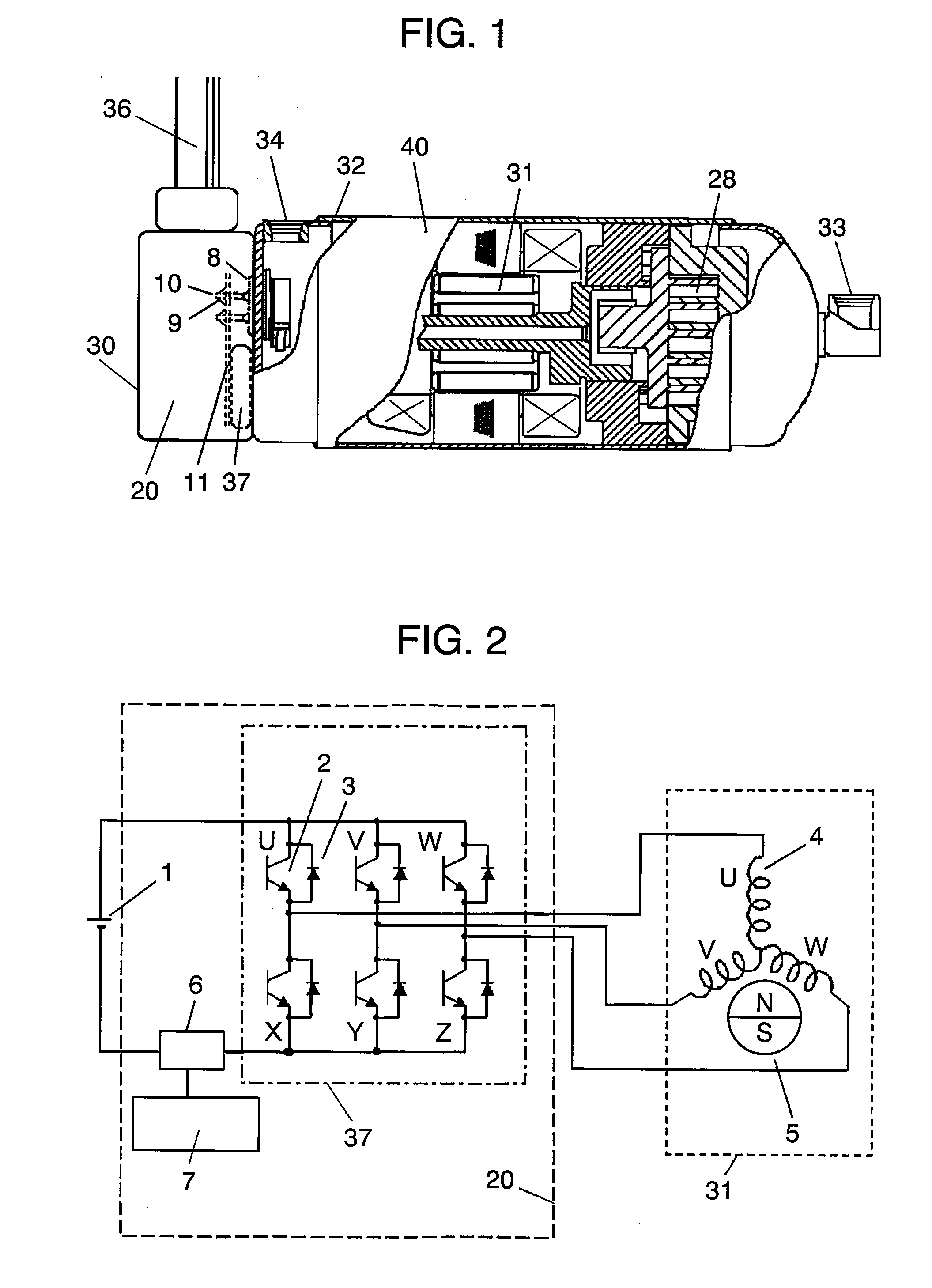
[0033]FIG. 1 is a sectional view showing the electrically driven compressor integrally formed with an inverter device, with the essential part cut away, in accordance with a first exemplary embodiment of the present invention. It shows a structure where inverter device 20 is attached on the left side of electrically driven compressor 40. In the structure, metal housing 32 accommodates compression mechanism section 28, motor 31 and the like.

[0034]Refrigerant is sucked through inlet 33 and then compressed by compression mechanism section 28, (although a scroll mechanism is used in the example) driven by motor 31. The compressed refrigerant cools motor 31 while passing by the motor and then goes out of outlet 34.

[0035]Inverter device 20 contains case 30 so as to be attachable to electrically driven compressor 40. Inverter circuit 37, which is the main heat source of inverter device 20, dissipates heat via case 30 to metal housing 32 of compressor 40. That is, refrigerant in compressor ...

second exemplary embodiment

[0049]The description given in the first embodiment focuses on pin terminal 10 of electric connection terminal 8 that connects between inverter device 20 and motor 31. When temperature sensor 18 is disposed inside metal housing 32 of compressor 40 to detect temperature of the winding of motor 31 and the like, pin terminal 10 is also used for establishing electrical connections between inverter device 20 and temperature sensor 18.

[0050]FIG. 6A is an electric circuit diagram showing the aforementioned structure in accordance with the second exemplary embodiment. A low voltage of approx. 5V of DC power source 19 is divided by voltage-dividing resistor 17, temperature sensor 18 (for example, thermistor 18). The both ends of thermistor 18 have electrical connections via pin terminal 10.

[0051]Pin terminal 10, since being structured of a metal with high thermal conductivity and a metal with low thermal conductivity, has contact-potential difference. The difference is small but cannot be ig...

third exemplary embodiment

[0058]FIG. 7 shows an example in which the electrically driven compressor integrally formed with the inverter device is mounted on a vehicle. Electrically driven compressor 61 with the inverter device, outdoor heat-exchanger 63 and outdoor fan 62 are disposed in the engine room forward of the vehicle. In the interior of the vehicle, indoor fan 65, indoor heat-exchanger 67 and air conditioning controller 64 are disposed. Captured through air inlet 66, outside air undergoes heat exchange in indoor heat-exchanger 67 and then flows into the interior of the vehicle.

[0059]Vehicles, in particular, electric vehicles and hybrid vehicles need a compact and lightweight air conditioner in terms of attainment of reliable driving performance and constraints on the installation space. Under the circumstances, it has become a critical challenge for an electrically driven compressor that reducing its size and weight so as to be disposed in the space-limited engine room or other narrow spaces.

[0060]T...


PUM


Abstract

The electrically driven compressor integrally formed with an inverter device contains compression mechanism section (28); motor (31) as a power source of the compression mechanism section; metal housing (32) for accommodating the compression mechanism section and the motor; inverter device (20), which is disposed outside the metal housing, for supplying electricity to the motor; and electric connection terminal (8) for electrically connecting between an inside and an outside of the metal housing. The electric connection terminal has pin terminal (10) formed of a metal with low thermal conductivity and a metal with high thermal conductivity plated on the metal with low thermal conductivity. The pin terminal is electrically connected to the inverter device by solder (9).

Description

[0001]This application is a U.S. National Phase application of PCT International Application PCT / JP2005 / 008141.TECHNICAL FIELD[0002]The present invention relates to an electrically driven compressor integrally formed with an inverter device, a motor and a compression mechanism section.BACKGROUND ART[0003]FIG. 8 shows electrically driven compressor 106 having a sensorless DC brushless motor as an example of conventional electrically driven compressors. In FIG. 8, metal housing 132 accommodates compression mechanism section 128, motor 131 and the like. Refrigerant is sucked through inlet 133 and then compressed by compression mechanism section 128, (although a scroll mechanism is used in the example) driven by motor 131. The compressed refrigerant cools motor 131 while passing by the motor and then goes out of outlet 134.[0004]Hermetically disposed, electric connection terminal 139 penetrates through metal housing 132 so as to be connected to a winding of motor 131 inside metal housin...

Claims


Application Information

Patent Timeline
IPC IPC(8): F04B39/00B60H1/22B60H1/32F04B17/03F04B39/12
CPCB60H1/3223B60L1/003B60L2210/40B60L2240/36F04B35/04F04B39/121Y02T10/7241F04C23/008F04C2240/30F04C2240/403F04C2240/803H01R2201/26F04C18/0215Y02T10/72
Inventor NISHII, NOBUYUKIGOTO, NAOMI
Owner PANASONIC CORP
Learn More