Backlight for liquid crystal display
a liquid crystal display and backlight technology, applied in the direction of illuminated signs, display means, instruments, etc., can solve problems such as the risk of breakage, and achieve the effect of simplifying assembly work and reducing production costs
- Summary
- Abstract
- Description
- Claims
- Application Information
AI Technical Summary
Benefits of technology
Problems solved by technology
Method used
Image

Examples
first embodiment
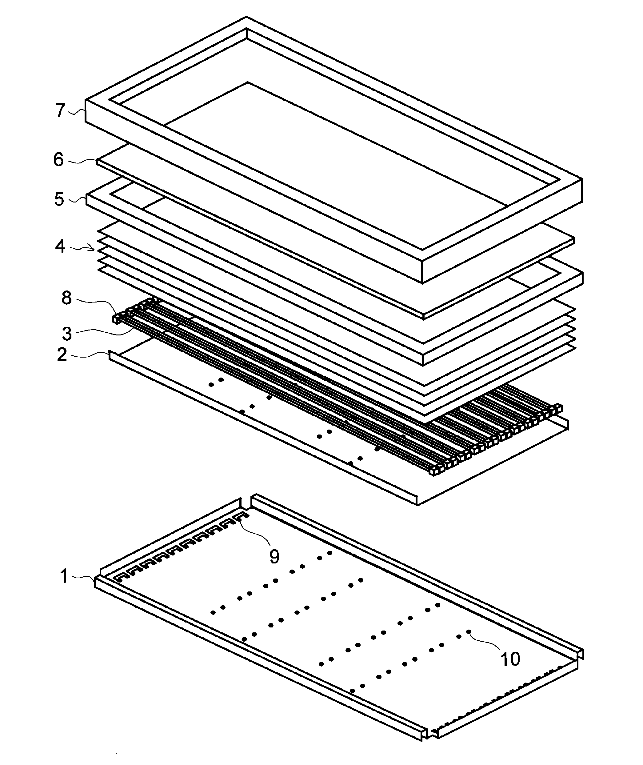
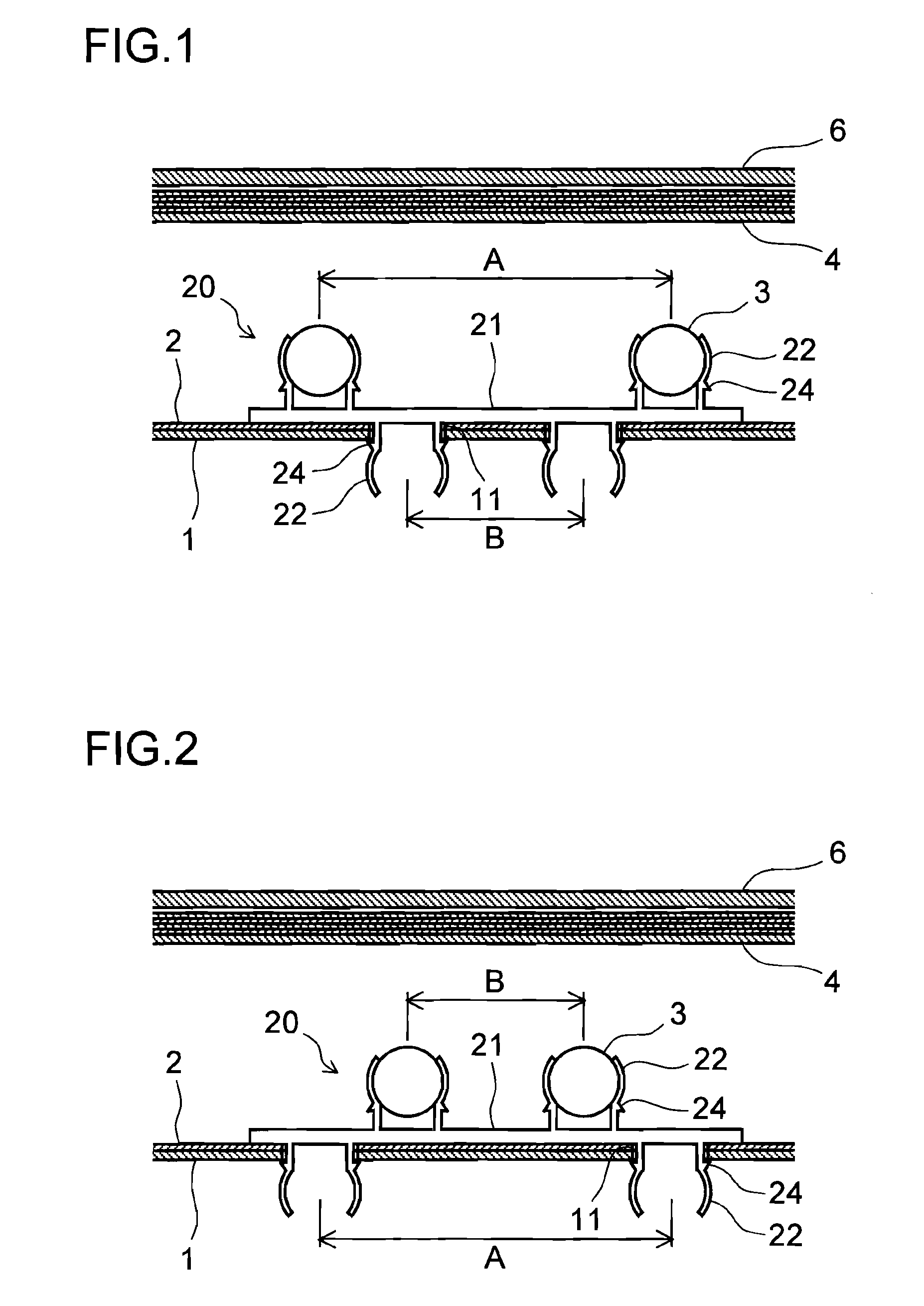
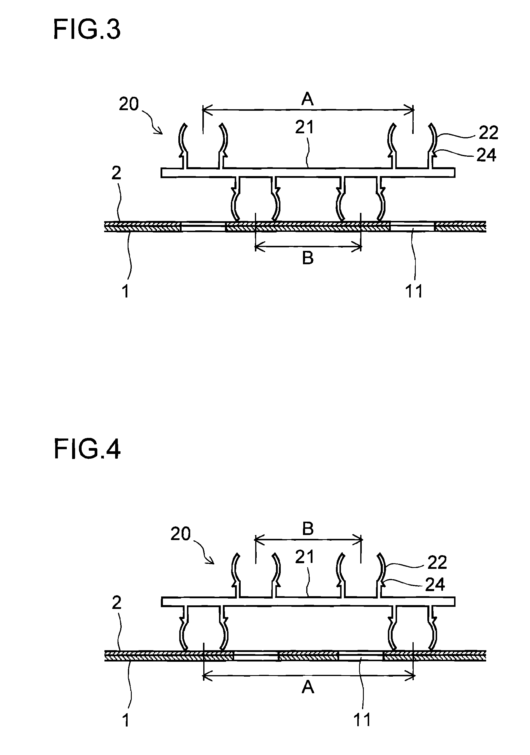
[0066]In a lamp clip 20 two lamp grippers 22 are formed integrally on each of opposite surfaces of a base 21. The lamp grippers 22 are each formed by two arms each having a straight root portion and a curved portion, and the two arms are arranged at an interval with concave surfaces of the curved portions facing each other. The lamp gripper 22 holds a straight tube light source lamp 3 by gripping it between two concave surfaces of the curved portions. The lamp gripper 22 also serves to fix the lamp clip 20 to a backlight chassis 1. On each arm of the lamp gripper 22, there is formed an engaging protrusion 24 that projects outward from a border portion between the straight root portion, which stands from the base 21, and the curved portion. Two engaging protrusions 24 are provided in each of the lamp grippers 22, and they project in the opposite direction from each other.
[0067]On one surface of the base 21, the lamp grippers 22 are arranged closer to both ends of the base 21 at an i...
fourth embodiment
[0085]In the fourth embodiment, there is a point to consider. Specifically, when the interval B of the lamp grippers 22 on one surface is an integral multiple of the interval A of the lamp grippers 22 on the opposite surface, there may be a case in which the lamp clip 20 is fixed in a wrong orientation as shown in FIG. 11. The combination of the backlight chassis 1 and the reflector sheet 2 shown in FIG. 11 is the same as that shown in FIG. 10. Thus, three lamp grippers 22 at the intervals A are supposed to face down and be placed in three through holes 11. However, two lamp grippers 22 at the interval B are placed in the outermost through holes 11, and three lamp grippers 22 at the intervals A are facing up.
[0086]To prevent this, the interval B is deviated from the integral multiple of the interval A as shown in FIG. 12, so that the lamp grippers 22 at the interval B are prevented from entering the through holes 11 at the intervals A.
[0087]A fifth embodiment of the present inventio...
fifth embodiment
[0088]In the fifth embodiment, a point to consider is the arrangement of the engaging protrusions 24. Specifically, of the four lamp grippers 22 arranged at intervals A and of the three lamp grippers 22 arranged at intervals B, pairs of outermost two only have the engaging protrusions 24. Specifically, among the lamp grippers 22, those with the engaging protrusions 24 and those without them coexist.
[0089]As described above, with the structure in which, at either surface of the lamp clip 20, only two of the lamp grippers 22 have the engaging protrusion 24, it is not necessary to perform engaging work of the engaging protrusion 24 for all the lamp grippers 22 that pass through the through holes 11. By simply performing engaging work, at two places, whereby the engaging protrusions 24 are engaged with the edges of the through holes 11, it is possible to fix the lamp clip 20 to the backlight chassis 1. This speeds up the fixing work of the lamp clip. Moreover, with respect to the lamp g...
PUM
| Property | Measurement | Unit |
|---|---|---|
| structure | aaaaa | aaaaa |
| shape | aaaaa | aaaaa |
| elasticity | aaaaa | aaaaa |
Abstract
Description
Claims
Application Information
 - R&D
- Intellectual Property
- Life Sciences
- Materials
- Tech Scout
- Unparalleled Data Quality
- Higher Quality Content
- 60% Fewer Hallucinations
Browse by: Latest US Patents, China's latest patents, Technical Efficacy Thesaurus, Application Domain, Technology Topic, Popular Technical Reports.
© 2025 PatSnap. All rights reserved.Legal|Privacy policy|Modern Slavery Act Transparency Statement|Sitemap|About US| Contact US: help@patsnap.com