
Electrical Machine

Inactive Publication Date: 2008-04-24
ROBERT BOSCH GMBH
View PDF9 Cites 4 Cited by
  • Summary
  • Abstract
  • Description
  • Claims
  • Application Information

AI Technical Summary

Benefits of technology

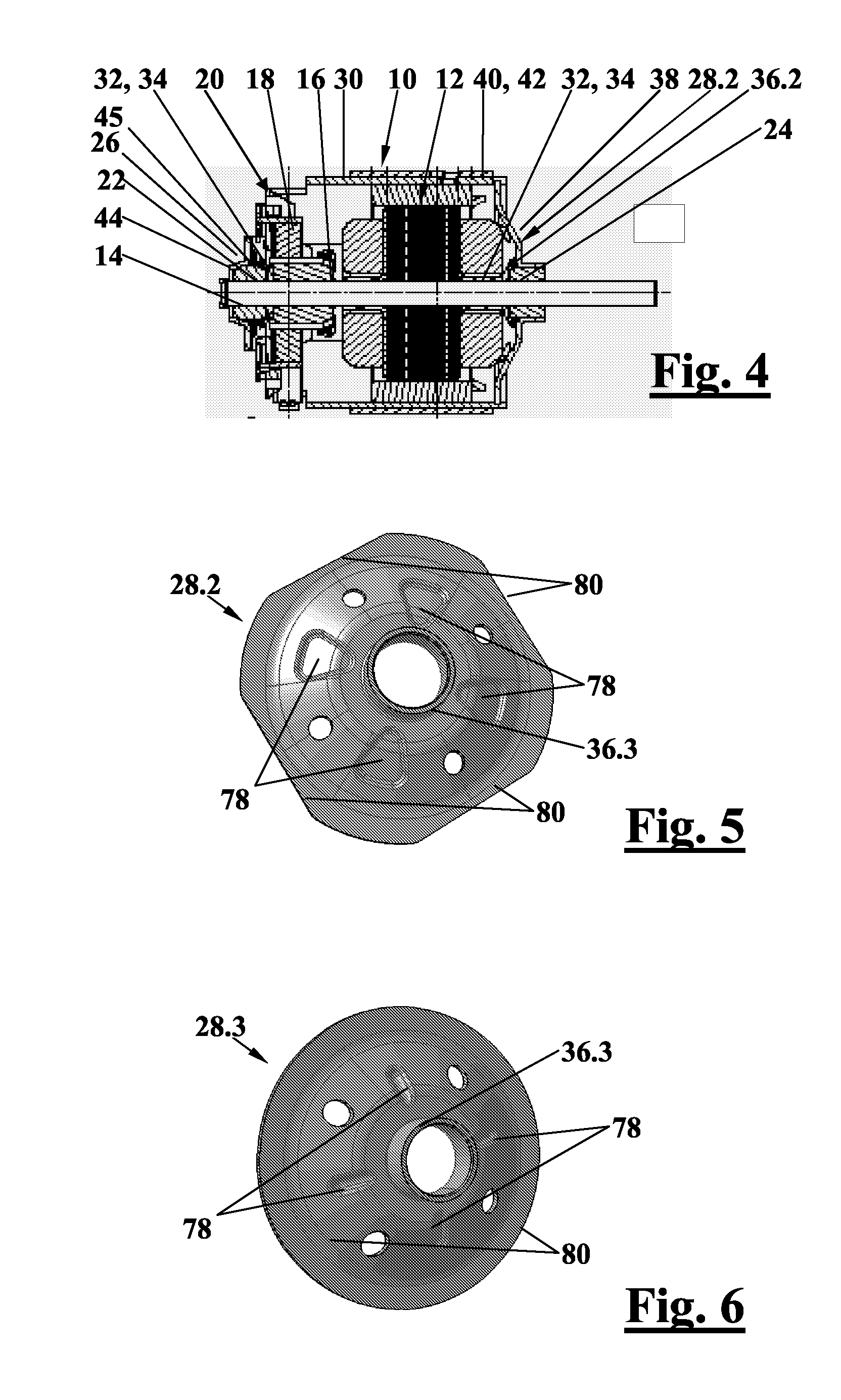
[0006] Preferably, the end shield has an outer edge, which is located on, and preferably rolled into, a pole ring of the electrical machine, and the outer edge is adjoined by a curved region, which protrudes from the pole ring of the electrical machine, and the sleeve is disposed in the curved region. This provides great strength of the combination in the axial direction, with easy production. The strength in the axial direction is increased if the end shield has at least one reinforcement for increasing the axial rigidity. Such a reinforcement can easily be produced in that at least the curved region has reinforcing beads, which preferably extend in the radial direction. Production is further simplified if the end shield a stamped and bent part.
[0007] If the sleeve protrudes into the electrical machine, then the curved region can be axially more rigid for the same height, and as a result the strength is increased. If the sleeve protrudes from the electrical machine, then the curved region can be designed more shallowly, making excellent utilization of the available volume possible, for instance for a fan wheel.
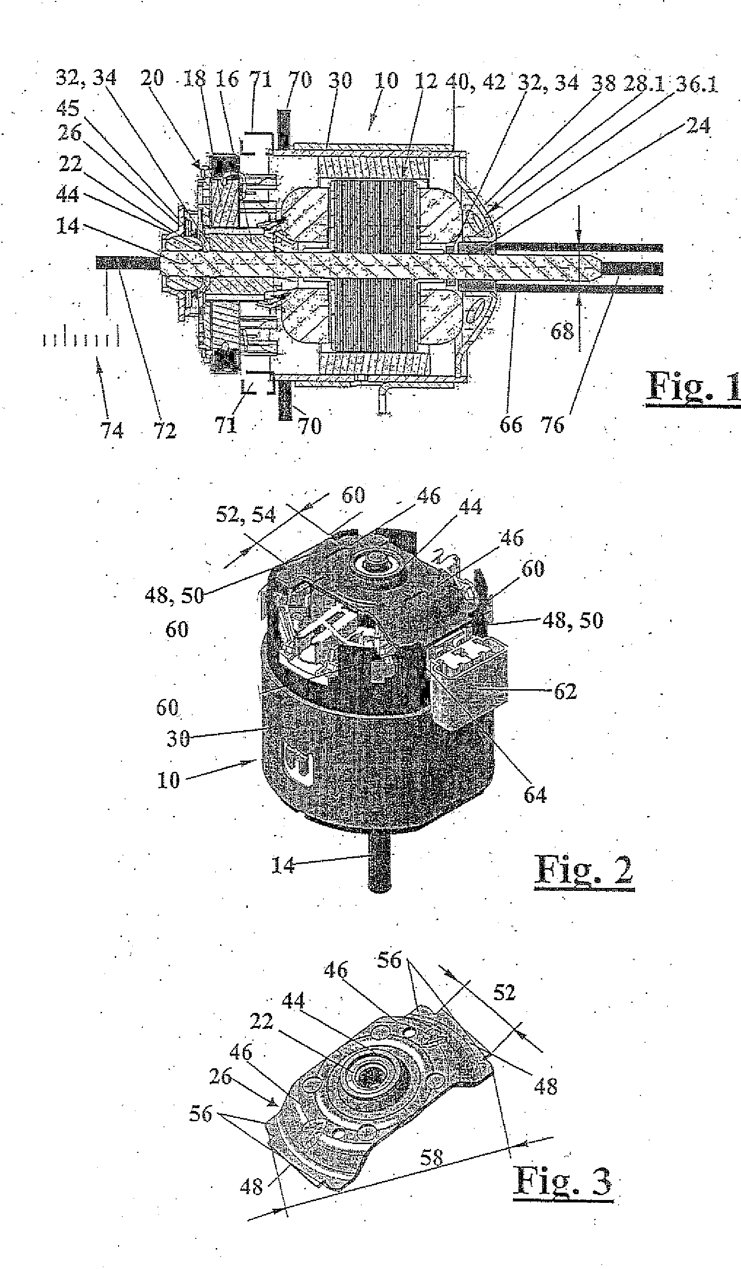
[0010] Because a second end shield, which is diametrically opposite the end shield having the cylindrical bearing, is secured in a pole ring of the electrical machine, and the second end shield has at least two brackets, protruding from the bearing seat for the bearing; because tabs on the brackets protrude outward and are inserted into recesses in the pole ring; and because next to the tabs, diametrically opposed stops are embodied, which are disposed inside the pole ring and whose diametral spacing is less than the inside diameter of the pole ring, so that the second end shield is supported in floating fashion before assembly, the bearings can easily be axially aligned. The risk of rough operation is minimized.
[0015] If the bearings of the electrical machine are not aligned quite precisely, it can happen that the shaft runs roughly. To prevent this, it is proposed that after the connection of the pole ring and the end shield that has the cylindrical bearing, the shaft is put in place, and after that an end shield, which is diametrically opposite the end shield of the cylindrical bearing, is placed upon assembly into the pole ring with radial play and is thrust onto the shaft, so that the end shield is aligned, and only then is it wedged to the pole ring.
[0010] Because a second end shield, which is diametrically opposite the end shield having the cylindrical bearing, is secured in a pole ring of the electrical machine, and the second end shield has at least two brackets, protruding from the bearing seat for the bearing; because tabs on the brackets protrude outward and are inserted into recesses in the pole ring; and because next to the tabs, diametrically opposed stops are embodied, which are disposed inside the pole ring and whose diametral spacing is less than the inside diameter of the pole ring, so that the second end shield is supported in floating fashion before assembly, the bearings can easily be axially aligned. The risk of rough operation is minimized.
[0011] Furthermore, a method for adjusting the axial play of the shaft of such an electrical machine is provided, in which the electrical machine is installed with an axial play that is greater than the specified axial play; the electrical machine is fixed; the shaft is pressed against one of the bearings; the shaft is then displaced in the direction of the other bearing, and the displacement distance until the shaft is pressed against the other bearing is measured; and the cylindrical bearing is pressed in the direction of the other bearing until the specified axial play is reached.
[0011] Furthermore, a method for adjusting the axial play of the shaft of such an electrical machine is provided, in which the electrical machine is installed with an axial play that is greater than the specified axial play; the electrical machine is fixed; the shaft is pressed against one of the bearings; the shaft is then displaced in the direction of the other bearing, and the displacement distance until the shaft is pressed against the other bearing is measured; and the cylindrical bearing is pressed in the direction of the other bearing until the specified axial play is reached.
[0013] Because a dimension by which the end shield, in which the cylindrical bearing is located, bends at least elastically upon pressing in of the cylindrical bearing is ascertained; and because the cylindrical bearing is additionally pressed by this dimension farther into the bearing seat, the axial play can be adjusted still more precisely.
[0014] If the shaft, after the adjustment of the axial play, is again pressed against one of the bearings and is then displaced in the direction of the other bearing, and the displacement distance until the shaft is pressed against the other bearing is measured again, and the re-measured displacement distance is compared with a predetermined value, then quality control can also be performed at the same station, making it possible to dispense with one subsequent station. If the re-measured displacement distance is too great, the method for adjusting the axial play is simply repeated.

Problems solved by technology

The primary task is to keep a certain axial play between the bearings and the armature free, in order to cover a temperature range of from −40° C. to +80° C. The axial play should, however, not be too great, since that has an adverse effect on noise or the vibration behavior (so-called axial vibration) and the service life of the motor.

Method used


Image

  • Electrical Machine
  • Electrical Machine
  • Electrical Machine

Examples


Embodiment Construction

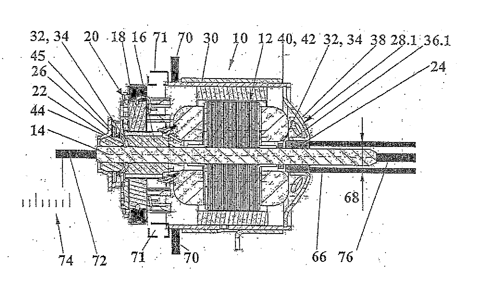
[0025] In FIG. 1, a rotating electrical machine is shown in simplified form in a longitudinal section. The electrical machine is an electric motor 10, which is used in a motor vehicle, for instance in a power window system, a wiper drive mechanism, or preferably a heater and / or blower drive mechanism, and so forth. However, it may also be a generator.

[0026] The electric motor 10 has a wound armature 12, which is disposed on a shaft 14. The armature 12 is connected to a commutator 16, which is connected by brushes 18 of a brush holder 20. Instead of the commutator 16, a collector of a generator may be provided.

[0027] The shaft 14 is supported in a spherical bearing 22 and a cylindrical bearing 24. In the present exemplary embodiment, the bearings 22, 24 are sintered bearings or slide bearings, which are saturated with oil. The spherical bearing 22 is disposed on a bearing bracket 26 in the region of the brush holder 20. The cylindrical bearing 24 is disposed on the power takeoff si...


PUM

PropertyMeasurementUnit
temperatureaaaaaaaaaa
displacement forceaaaaaaaaaa

Abstract

An electrical machine, preferably a blower drive mechanism for a motor vehicle, having a shaft which is supported in at least two bearings with a specified axial play; a cylindrical bearing is secured in a bearing seat of an end shield and rests directly on the bearing seat. The cylindrical bearing has a cylindrical outer circumference, and the bearing seat is a sleeve with a cylindrical inside diameter, into which sleeve the cylindrical bearing is secured with a press fit on the outer circumference and is held axially in the bearing seat by the thus-attained frictional engagement. This has the advantage that more-precise adjustment of the longitudinal play of the armature is possible. Moreover, no additional components such as retaining springs are necessary.

Description

PRIOR ART [0001] The invention is based on an electrical machine as generically defined by the preamble to claim 1. [0002] An electrical machine of this kind, such as a blower drive mechanism for a motor vehicle, includes a, which is placed with axial play in at least two bearings, and at least one bearing is secured in a bearing seat of an end shield and rests directly on the bearing seat. [0003] In electric motors of the kind that are typically used for heater and air conditioner motors, stringent demands are made with regard to the longitudinal armature play. The axial play, which should amount to 0.1 to 0.3 mm, for instance, is an essential variable for assuring the function of the electric motor. The primary task is to keep a certain axial play between the bearings and the armature free, in order to cover a temperature range of from −40° C. to +80° C. The axial play should, however, not be too great, since that has an adverse effect on noise or the vibration behavior (so-called...

Claims


Application Information

Patent Timeline
Patent Type & Authority Applications(United States)
IPC IPC(8): H02K5/16H02K15/16H02K5/15
CPCH02K5/1672H02K15/16Y10T29/49012Y10T29/49945Y10T29/53078H02K5/16
Inventor WINKLER, WOLFGANGHEIDRICH, MARKUSSEEBACHER, HANS-PETERSILVA, FERNANDOERNST, CHRISTIAN
Owner ROBERT BOSCH GMBH
Learn More