Rod integrator holder and projection type video display

a technology of integrator holders and video displays, applied in the field of rod integrator holders, can solve problems such as difficult to ensure the accuracy of the abovementioned conventional rod integrator holders

Inactive Publication Date: 2008-04-03
SANYO ELECTRIC CO LTD
View PDF1 Cites 0 Cited by
  • Summary
  • Abstract
  • Description
  • Claims
  • Application Information

AI Technical Summary

Benefits of technology

[0006]In view of the aforementioned circumstances, it is an object of the present invention to provide a rod integrator holder which enables ensuring the machining accuracy of the rod integrator holder itself relatively easily and also making the optical axis center of a tapered rod integrator coincident with an illumination optical axis as much as possible, even when sufficient machining accuracy of the shape of the tapered rod integrator is not ensured.
[0008]The aforementioned rod integrator holder is constituted by the fixed-side supporting member having the first holding portion, the guide portion and the second holding portion having the second opening, which eliminates the necessity of forming rod holding portions by working on the inside of a tubular member as in a conventional rod integrator holder, thereby enabling ensuring the accuracy of the rod integrator holder itself relatively easily. Furthermore, the aforementioned slide supporting member is slidable in parallel to the illumination optical axis by the aforementioned guide portion, and the aforementioned tapered rod integrator is positioned and held at the halfway position of the body portion thereof through the second opening of the slide supporting member. This enables making the optical axis center of the tapered rod integrator coincident with the illumination optical axis as much as possible and also preventing the occurrence of wobbles in the aforementioned holding as much as possible, even when sufficient accuracy of the shape of the tapered rod integrator is not ensured.
[0012]The rod integrator holder according to the present invention eliminates the necessity of forming rod holding portions by working on the inside of a tubular member as in a conventional rod integrator holder, thereby enabling ensuring the accuracy of the rod integrator holder itself relatively easily. This enables making the optical axis center of the tapered rod integrator coincident with the illumination optical axis as much as possible, even when sufficient accuracy of the shape of the tapered rod integrator is not ensured. This offers the advantage of not requiring assembly-workers to have specific skills for making the optical axis center of the tapered rod integrator coincident with the optical axis center of the illuminating system as much as possible.

Problems solved by technology

However, conventional rod integrator holders as aforementioned may cause inconvenience such as disagreement of the optical axis center of the tapered rod integrator with the illumination optical axis, in cases where sufficient accuracy of the shape of the tapered rod integrator is not ensured.
However, it can be considered that ensuring the accuracy of the aforementioned conventional rod integrator holder is not easy, because the aforementioned two holding portions are obtained by working on the inside of a tubular member.

Method used


Image

  • Rod integrator holder and projection type video display
  • Rod integrator holder and projection type video display
  • Rod integrator holder and projection type video display

Examples


Embodiment Construction

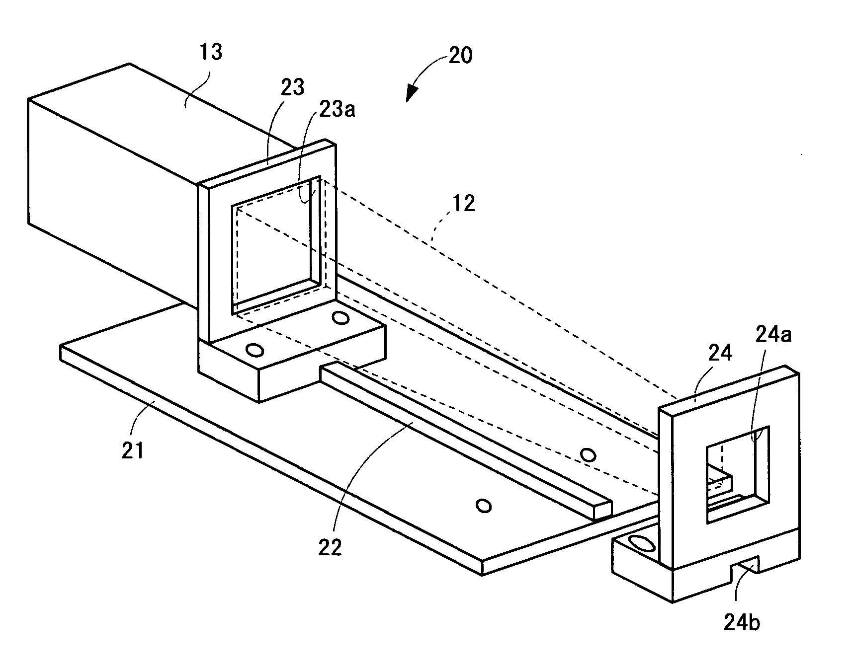
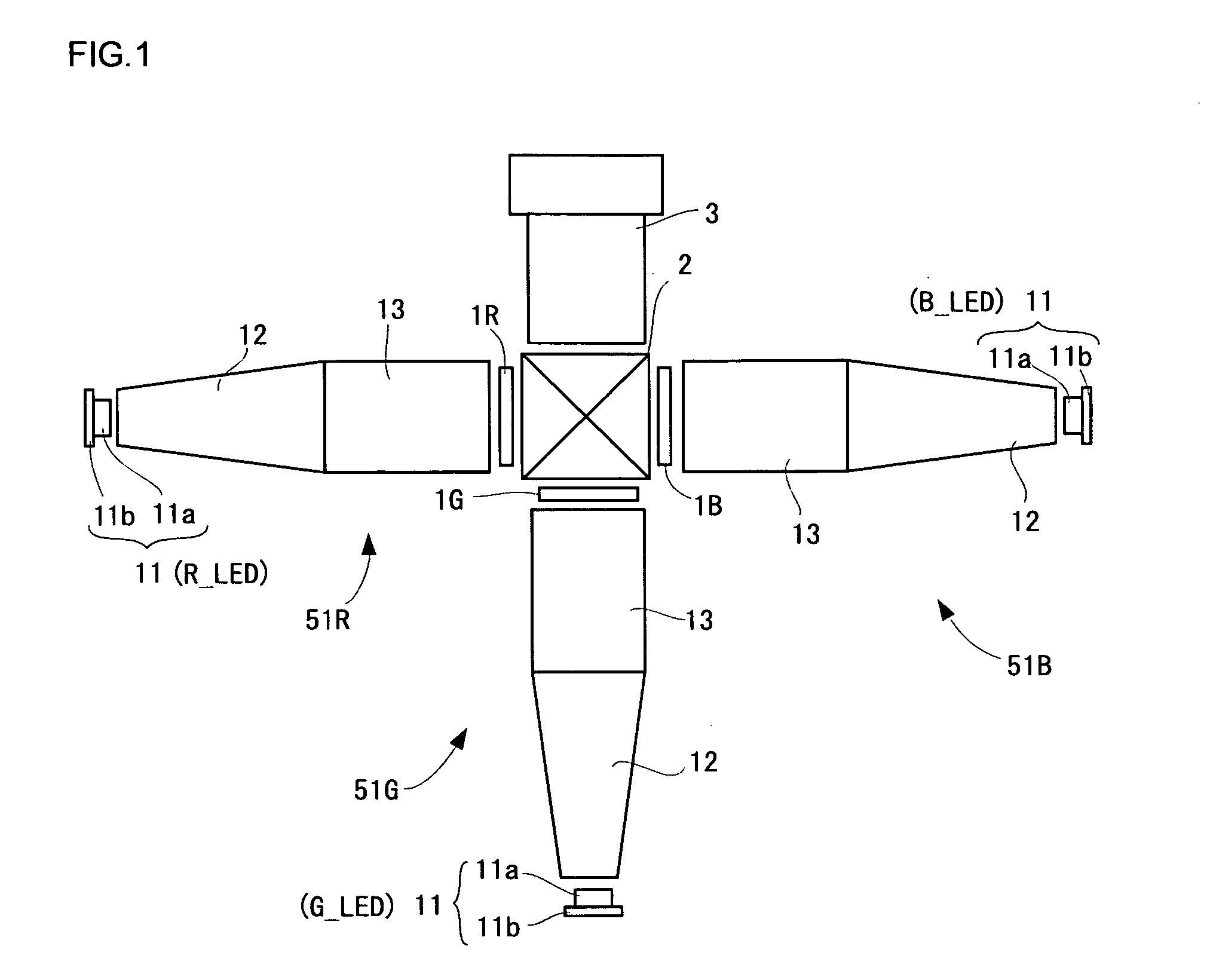
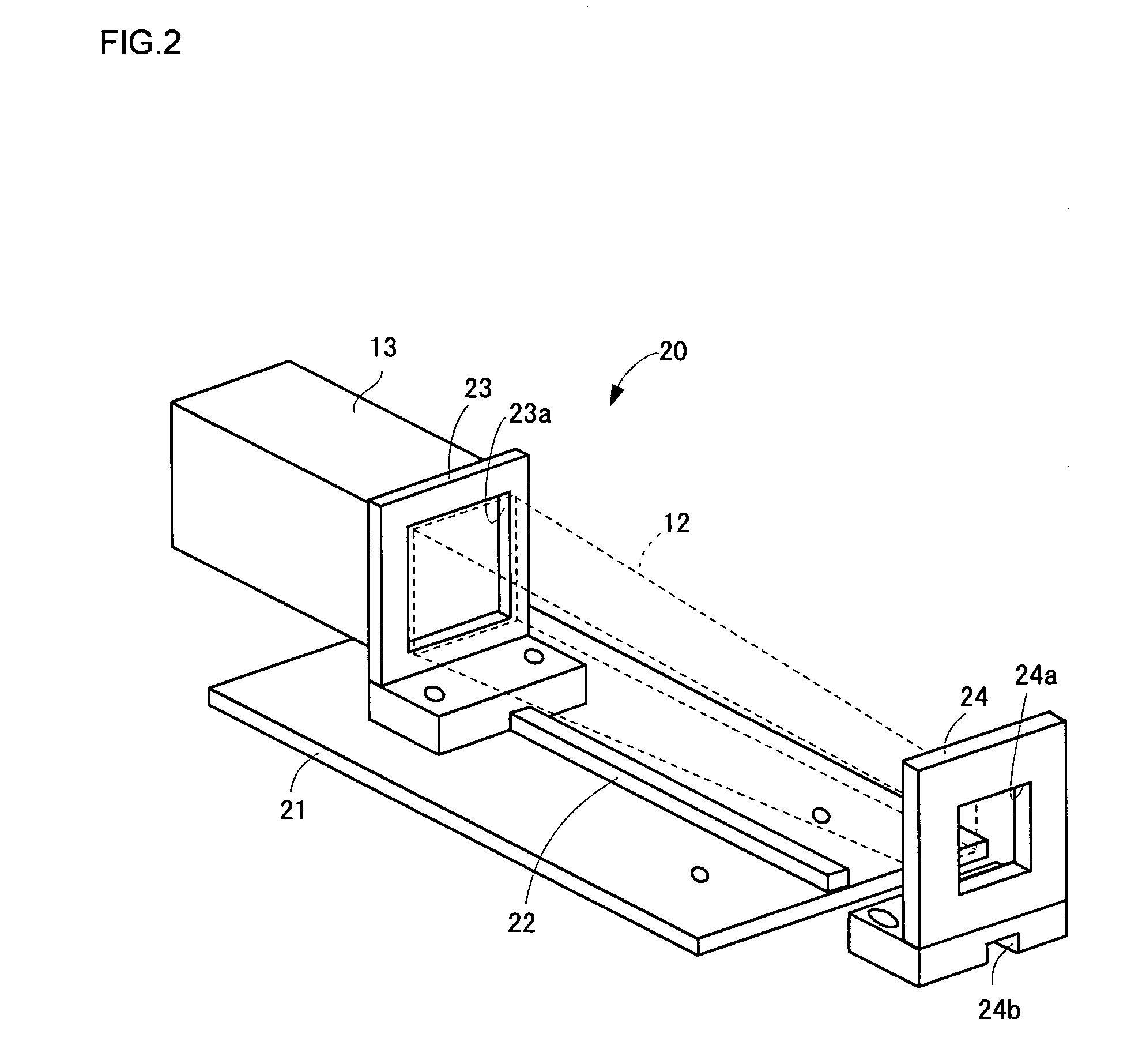
[0028]Hereinafter, with reference to FIGS. 1 to 14, an embodiment of the present invention will be described.

[0029]FIG. 1 is an explanation view illustrating an optical system in a projection type video display. This projection type video display includes three illuminating devices 51R, 51G and 51B. Each illuminating device 51 includes an LED (light-emitting diode) 11 as a light source, a tapered rod integrator (hereinafter, referred to as a tapered rod) 12, and a rectangular-parallelepiped rod integrator (hereinafter, referred to as an extension rod) 13. Further, at the light exit side of each illuminating device 51, there is placed a liquid crystal display panel 1R, 1G or 1B as a light valve.

[0030]The aforementioned LED 11 is constituted by an LED chip 11a and a heat sink (heat releasing plate) 11b. The LED chip 11a in the illuminating device 51R emits red light, the LED chip 11a in the illuminating device 51G emits green light, and the LED chip 11a in the illuminating device 51B ...


PUM


Abstract

A guide convex portion is formed on a base plate in parallel to an illumination optical axis. Further, a fixed-side supporting member is provided in the base plate. A first opening is formed in an upright portion of the fixed-side supporting member. A slide supporting member can be provided on the base plate. A second opening is formed in the upright portion of the slide supporting member. By inserting a tapered rod into the second opening at its light incidence side and by moving the slide supporting member along the aforementioned guide convex portion, the slide supporting member is stopped at a predetermined position and, at this position, the slide supporting member is fixed.

Description

BACKGROUND OF THE INVENTION[0001]1. Field of the Invention[0002]The present invention relates to a rod integrator holder for holding a tapered rod integrator and a projection type video display including the same.[0003]2. Description of Related Art[0004]In recent years, attempts have been made to mount, on projection type video display, an illuminating system employing tapered rod integrators for reducing the divergence angles of light emitted from light sources such as LEDs and for reducing the luminance non-uniformity within the light illumination surfaces. Further, there have been proposed rod integrator holders for holding the tapered rod integrators (refer to Japanese Unexamined Patent Publication No. 2004-94115).SUMMARY OF THE INVENTION[0005]However, conventional rod integrator holders as aforementioned may cause inconvenience such as disagreement of the optical axis center of the tapered rod integrator with the illumination optical axis, in cases where sufficient accuracy of ...

Claims


Application Information

Patent Timeline
IPC IPC(8): G03B21/14G02B7/02
CPCG02B27/0006H04N9/3152G03B21/14G02B27/0994G02B1/10G03B21/208
Inventor MIWA, TAKASHIKONDOU, NOBUYUKIYOKOTE, YOSHIHIRO
Owner SANYO ELECTRIC CO LTD
Why Eureka
Try Eureka