
Non-destructive testing of pipes

a condition assessment and non-destructive technology, applied in the direction of instruments, heat measurement, specific gravity measurement, etc., can solve the problems of pipe failure, pipe wall thickness reduction, and high cost of pipe excavating for the purpose of measuring wall thickness, so as to achieve easy implementation and easy measurement and calculation of pipe wall thickness

Active Publication Date: 2008-04-03
MUELLER INT LLC
View PDF12 Cites 17 Cited by
  • Summary
  • Abstract
  • Description
  • Claims
  • Application Information

AI Technical Summary

Benefits of technology

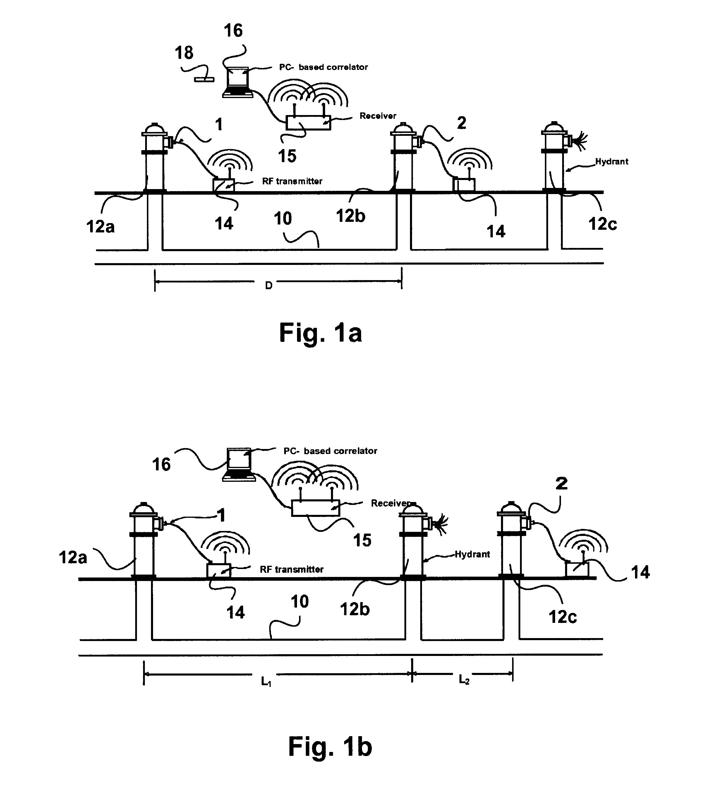
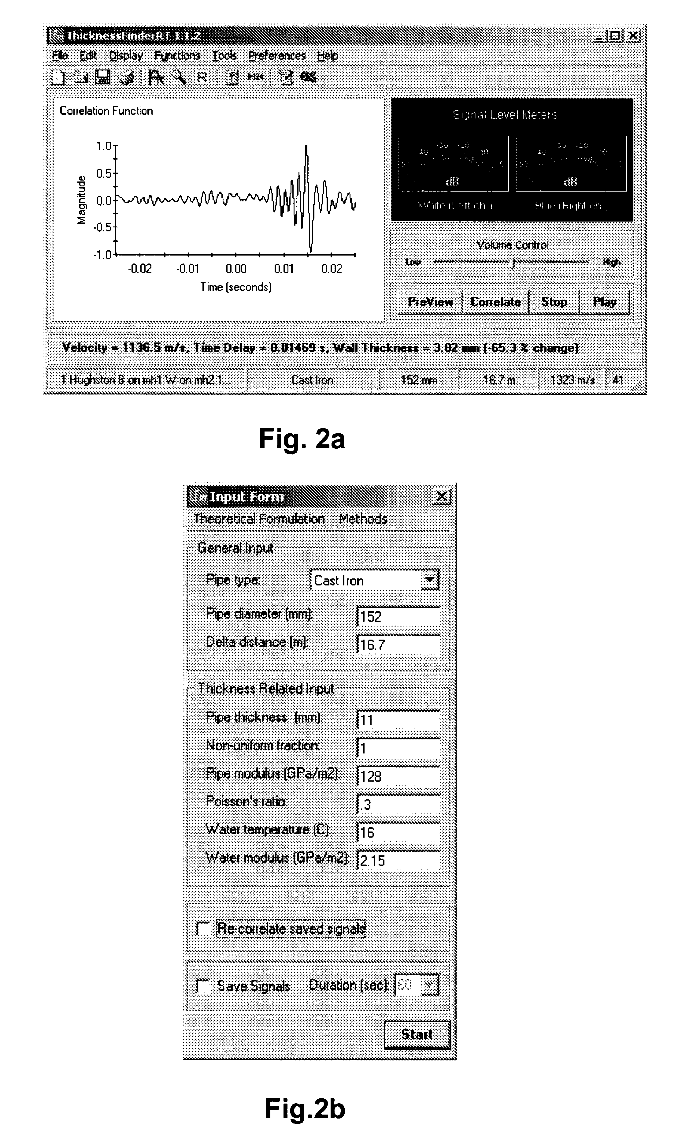
[0012] The method in accordance with the invention has the advantage of being non-destructive and non-intrusive. All required measurements can be made from the ground surface. The length of the pipe section represented by the average profile can be arbitrarily chosen. Initially, a 100 metres long section, which is the usual distance between fire hydrants in urban areas, can be chosen. Subsequently, if higher resolution is needed, small access holes to the pipe may be drilled, e.g., using keyhole vacuum excavation technologies, to measure the thickness over shorter pipe sections. Alternatively, arrays of closely spaced hydrophones may be inserted into pipes through fire hydrants or corporation stops. The measurement and calculation of the pipe wall thickness can be easily made using Windows-based PC software. The proposed method is easy to implement (e.g., in conjunction with routine leak detection surveys). Also, it does not require a high level of operator skill.

Problems solved by technology

Buried pipes, such as pipes used in municipal water systems, lose metal resulting in a reduction in pipe wall thickness, as a result of internal and external corrosion.
Sustained wall thickness loss eventually causes the pipe to fail.
Excavating pipes for the purpose of measuring wall thickness is costly, as it requires excavating the pipe at several locations.
Also, thickness values based on the coupons may not be statistically representative of the overall condition of the pipe unless a very large number of locations are excavated.
Data acquisition and analysis is very intensive and expensive.
It is not suitable for water distribution systems, which are geometrically complex and extensive networks comprised of small-diameter pipes that are usually filled with debris and have no pig launching stations.

Method used


Image

  • Non-destructive testing of pipes
  • Non-destructive testing of pipes
  • Non-destructive testing of pipes

Examples


Embodiment Construction

[0020] In order to assist in understanding the invention, it is helpful to consider the underlying theory.

[0021] The propagation velocity of acoustic waves in an unbounded fluid body is defined by the following equation:

νo=√{square root over (γk / ρ)}  (1)

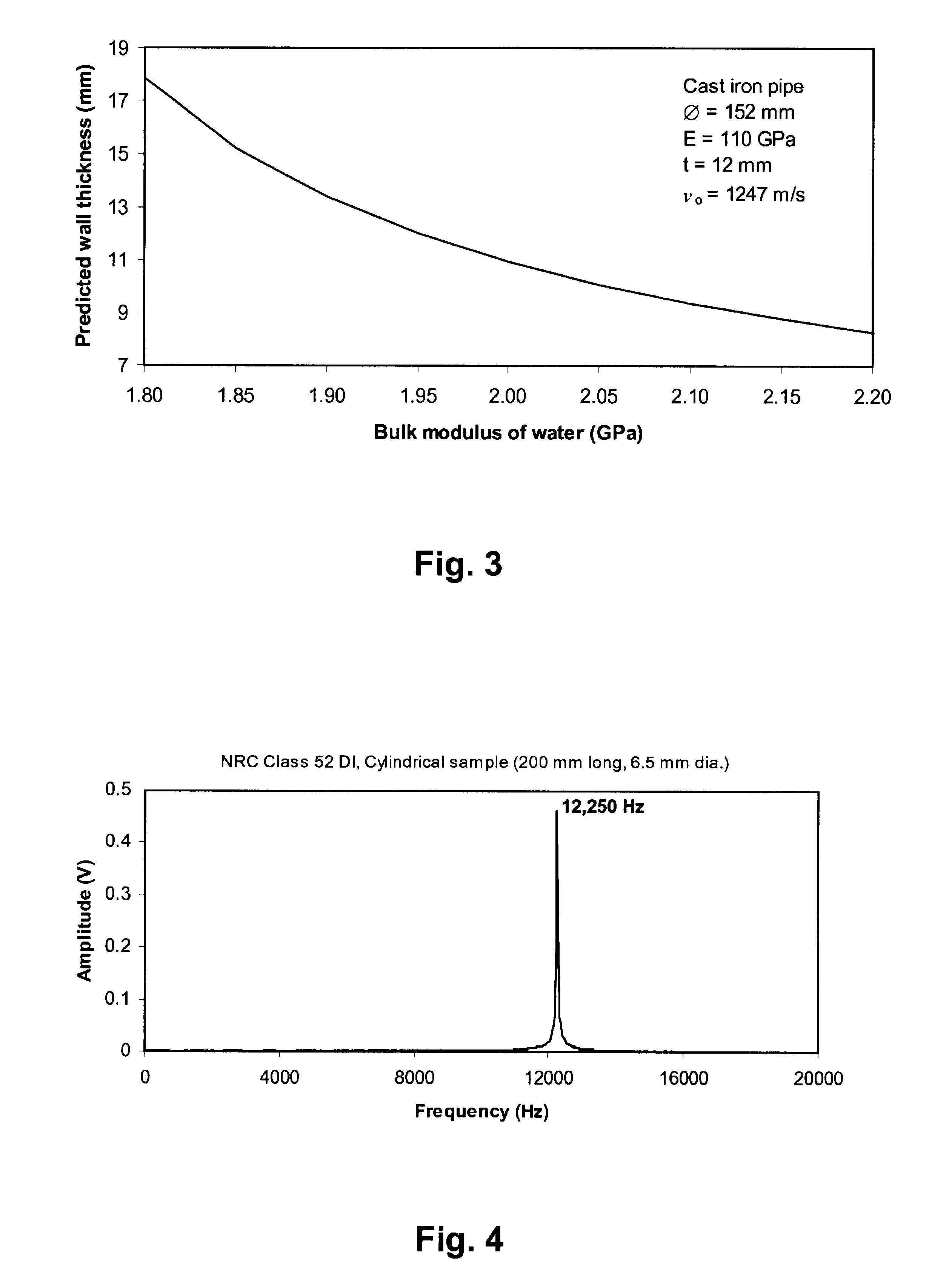
where K is the bulk modulus of elasticity of the fluid, ρ is its density, and γ is the ratio of the specific heats of the fluid (i.e., the ratio of the fluid's heat capacity in a constant pressure process to the heat capacity in a constant volume process).

[0022] The derivation of this equation can be found in Pearsall, I. S. “The velocity of water hammer waves”, Proceedings of the Institution of Mechanical Engineers, Vol. 180, Part 3E, pp. 12-20, 1965, the contents of which are herein incorporated by reference.

[0023] For a nearly incompressible liquid, which is the case under normal temperatures and pressures in water distribution pipes, γ is approximately equal to unity. Then, Eq. (1) becomes:

νo=√{square root over (K / ρ)}  (2)...


PUM


Abstract

To perform a non-destructive condition assessment of a pipe carrying a fluid, an actual value representative of the propagation velocity of an acoustic disturbance propagating between two longitudinally separated points on the pipe is determined. A corresponding predicted value for the propagation velocity is computed as a function of at least one wall thickness parameter of the pipe by using a theoretical model for the propagation of acoustic waves in the pipe that assumes said pipe has a finite wall thickness with a predetermined circumferential thickness profile. The wall thickness parameter is then computed by matching the actual value with the predicted value, for example, by substituting the actual value in a formula predicting the theoretical value.

Description

CROSS REFERENCE TO RELATED APPLICATION [0001] This application is a divisional under 35 USC 121 of prior U.S. application Ser. No. 11 / 156,573, filed Jun. 21, 2005, the contents of which are herein incorporated by reference.FIELD OF THE INVENTION [0002] This invention relates to the non-destructive condition assessment of pipes, and in particular buried pipes or pipes that are otherwise inaccessible, such as fire sprinkler systems and pipelines in the oil and gas industry. BACKGROUND OF THE INVENTION [0003] Buried pipes, such as pipes used in municipal water systems, lose metal resulting in a reduction in pipe wall thickness, as a result of internal and external corrosion. Sustained wall thickness loss eventually causes the pipe to fail. Such pipes have to be periodically inspected and evaluated for structural adequacy. Accurate information about pipe wall thickness is needed to determine the structural capacity of pipes. Also, monitoring of pipe metal loss is needed to estimate the ...

Claims


Application Information

Patent Timeline
Patent Type & Authority Applications(United States)
IPC IPC(8): G01H5/00
CPCG01B17/02G01M3/243G01N29/07G01N29/222G01N2291/2634G01N2291/011G01N2291/02827G01N2291/02854G01N29/4418
Inventor HUNAIDI, OSAMABRACKEN, MARCWANG, ALEX
Owner MUELLER INT LLC
Learn More