
Film formation apparatus for semiconductor process and method for using the same

a technology of film formation apparatus and semiconductor device, which is applied in the direction of liquid surface applicators, coatings, chemical vapor deposition coatings, etc., can solve the problems of deterioration of some components of processing apparatus, affecting the yield of semiconductor devices to be manufactured, and affecting the effect of cleaning

Active Publication Date: 2008-03-27
TOKYO ELECTRON LTD
View PDF28 Cites 8 Cited by
  • Summary
  • Abstract
  • Description
  • Claims
  • Application Information

AI Technical Summary

Benefits of technology

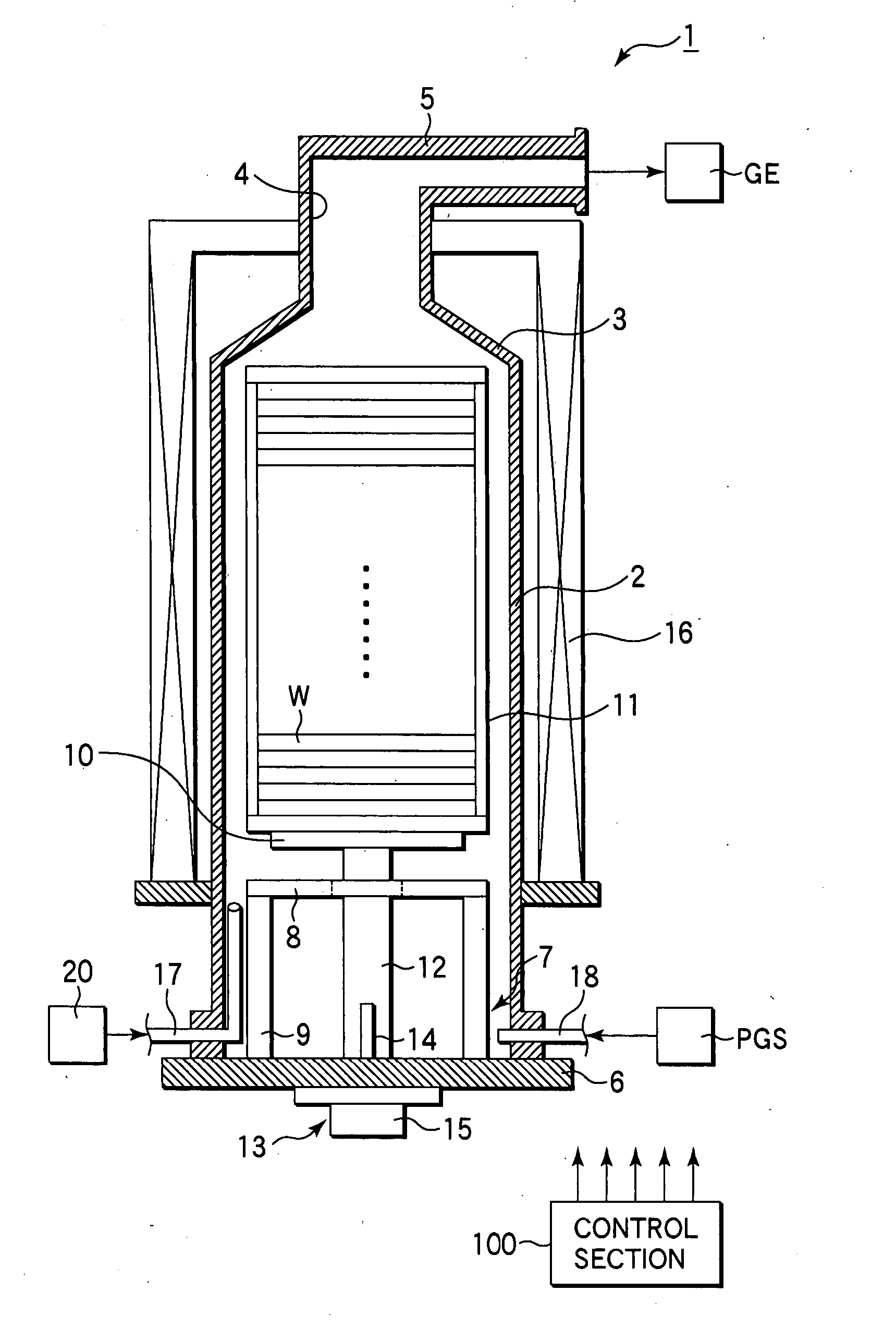
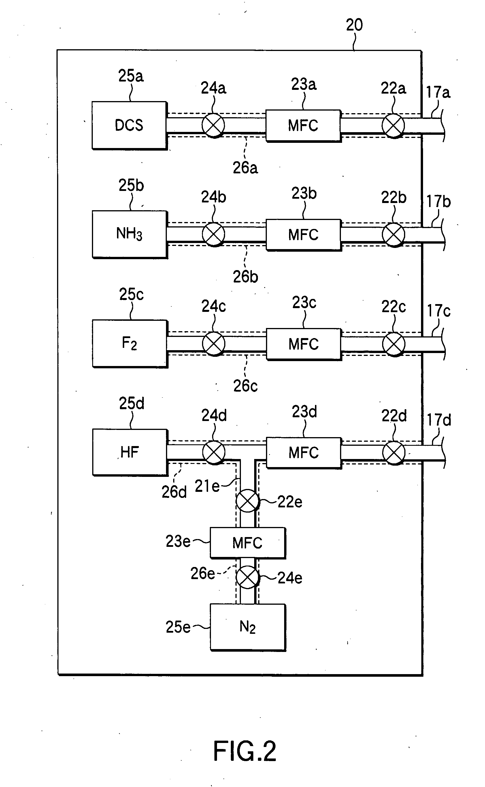
The present invention provides a film formation apparatus for a semiconductor process that can stably perform cleaning inside a reaction tube and prevent a decrease in yield of products and deterioration of components of the apparatus. The apparatus includes a reaction chamber, a heater, an exhaust system, a film formation gas supply circuit, a cleaning gas supply circuit, and a control section. The cleaning gas supply circuit includes an upstream gas passage between a gas supply source of a halogen acidic gas and a flow rate controller. The method involves forming a first atmosphere inside the upstream gas passage, supplying the halogen acidic gas through the upstream gas passage, and using the cleaning gas to etch and remove a by-product film deposited on the inner surface of the reaction chamber. The technical effects of the invention include stable cleaning and prevention of decrease in yield of products and deterioration of components of the apparatus.

Problems solved by technology

If the film formation process is continued while by-product films are present on the interior of the reaction tube, a stress is generated and causes peeling of some of the by-product films and the quartz of the reaction tube due to a difference in coefficient of thermal expansion between the quartz and by-product films.
Consequently, particles are generated, and may decrease the yield of semiconductor devices to be fabricated and / or deteriorate some components of the processing apparatus.
However, as described later, the present inventors have found that conventional cleaning methods of this kind may cause problems in that cleaning cannot be stably performed, the yield of products is decreased, and / or some components of apparatuses are deteriorate.

Method used


Image

  • Film formation apparatus for semiconductor process and method for using the same
  • Film formation apparatus for semiconductor process and method for using the same
  • Film formation apparatus for semiconductor process and method for using the same

Examples


Embodiment Construction

[0044] In the process of developing the present invention, the inventors studied problems with regard to conventional methods for cleaning the interior of a reaction tube used in a film formation apparatus for a semiconductor process. As a result, the inventors have arrived at the findings given below.

[0045] Conventionally, where a cleaning gas, such as hydrogen fluoride, is supplied into a reaction tube, the gas is supplied through a gas supply line set at, e.g., a temperature of from room temperature to 40° C. and a pressure of from atmospheric pressure to 131 kPa (985 Torr). In this case, the interior of the gas supply line may be corroded by liquefied hydrogen fluoride, whereby a metal compound, such as a metal fluoride, is deposited inside the reaction tube, and / or metal contamination occurs on wafers W. Further, particles are generated, and may decrease the yield of semiconductor devices to be fabricated and / or deteriorate some components of the processing apparatus. Further,...


PUM

PropertyMeasurementUnit
pressureaaaaaaaaaa
temperatureaaaaaaaaaa
pressureaaaaaaaaaa

Abstract

A method for using a film formation apparatus for a semiconductor process forms a first atmosphere inside an upstream gas passage between a gas supply source of a halogen acidic gas and a flow rate controller. The first atmosphere is set for the halogen acidic gas to have an average molecular weight of 20 or more and 23 or less. Further, the using method supplies the halogen acidic gas from the gas supply source through the upstream gas passage having the first atmosphere thus formed and the flow rate controller, thereby supplying a cleaning gas containing the halogen acidic gas into a reaction chamber of the film formation apparatus. A by-product film deposited on an inner surface of the reaction chamber is etched and removed by use of the cleaning gas thus supplied.

Description

BACKGROUND OF THE INVENTION [0001] 1. Field of the Invention [0002] The present invention relates to a film formation apparatus for a semiconductor process for forming a film on a target substrate, such as a semiconductor wafer, and also to a method for using the apparatus. The term “semiconductor process” used herein includes various kinds of processes which are performed to manufacture a semiconductor device or a structure having wiring layers, electrodes, and the like to be connected to a semiconductor device, on a target substrate, such as a semiconductor wafer or a glass substrate used for an FPD (Flat Panel Display), e.g., an LCD (Liquid Crystal Display), by forming semiconductor layers, insulating layers, and conductive layers in predetermined patterns on the target substrate. [0003] 2. Description of the Related Art [0004] In manufacturing semiconductor devices, a process, such as CVD (Chemical Vapor Deposition), is performed to form a thin film, such as a silicon oxide film...

Claims


Application Information

Patent Timeline
Patent Type & Authority Applications(United States)
IPC IPC(8): H01L21/31
CPCH01L21/3185C23C16/4405H01L21/02271H01L21/02211H01L21/0217
Inventor OKABE, TSUNEYUKIKATO, HITOSHI
Owner TOKYO ELECTRON LTD
Learn More