Image forming apparatus and image forming system

Inactive Publication Date: 2008-03-27
KONICA MINOLTA BUSINESS TECH INC
View PDF3 Cites 3 Cited by
  • Summary
  • Abstract
  • Description
  • Claims
  • Application Information

AI Technical Summary

Benefits of technology

[0008]An object of the present invention is to provide an image forming apparatus and image forming system that can form images safely with high throughput even post-processing units are cascaded.

Problems solved by technology

If the power supply is stopped by the home terminal described in Japanese unexamined patent application No. 6-121253 when the consumption current exceeds the allowable current, a series of operations performed by the image forming apparatus, that is, a print and bookbinding job being executed, is completely stopped, greatly reducing the productivity of printing and bookbinding.
Accordingly, some processing results may not satisfy user's requests.
However, the prolonged fixing time makes it hard to satisfy a request for high-speed printing.
With the image forming apparatus disclosed in Japanese unexamined patent application No. 2005-3886, as more optional units are connected, the current flowing in the optional units is increased, making it difficult to obtain the amount of current necessary for fixing.

Method used


Image

  • Image forming apparatus and image forming system
  • Image forming apparatus and image forming system
  • Image forming apparatus and image forming system

Examples


Embodiment Construction

[0024]An embodiment of the present invention will be described below in detail with reference to the drawings.

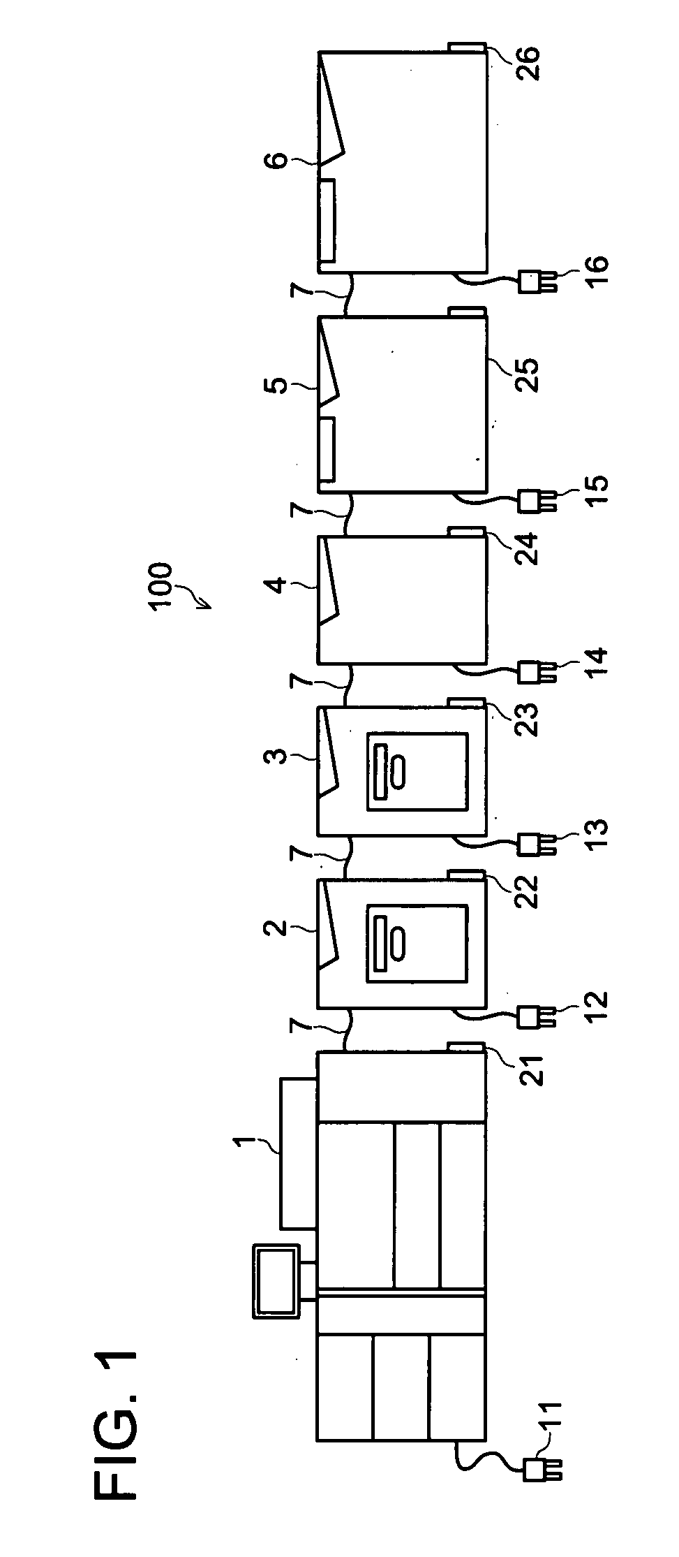
[0025]FIG. 1 schematically shows the structure of an image forming system according to this embodiment. As shown in FIG. 1, the image forming system 100 comprises an image forming unit 1 and post-processing units 2, 3, 4, 5, and 6. The image forming unit 1 is connected to the post-processing units 2 to 6 through a serial communication interface 7, enabling data communication among them. In FIG. 1, the image forming unit 1 and post-processing units 2 through units 6 are separated from one another to prevent the drawing from becoming complicated. In practice, however, the image forming unit 1 and post-processing units 2 through units 6 are disposed in tight contact with one another so that a recording media (referred to below as a paper sheet) such as a paper sheet is transferred from the image forming unit 1 to the post-processing units 2, 3, 4, 5, and 6 in that order.

[0026]T...


PUM


Abstract

An image forming apparatus having a main body unit for forming an image on a recording medium, connectable to at least one post-processing unit for performing post-processing for the recording medium on which the image is formed, the image forming apparatus includes, a current value acquiring portion for acquiring at least one of a calculated value of a current and a measured value of the current as a value of the current flowing through the main body unit, and a control portion for selecting an operation mode from a plurality of operation modes each having a distinct value of current flowing through the main body unit.

Description

RELATED APPLICATION[0001]This application is based on Japanese Patent Application No. 2006-258391 filed on Sep. 25, 2006 in Japanese Patent Office, the entire content of which is hereby incorporated by reference.FIELD[0002]The present invention relates to an image forming apparatus and image forming system for forming an image on a recording medium and, more particularly, an image forming apparatus and image forming system to which at least one post-processing unit for performing post-processing for the recording medium on which the image is formed can be connected.BACKGROUND OF THE INVENTION[0003]There are conventionally proposed image forming apparatuses that include a post-processing unit performing so-called post-processing, such as bookbinding achieved by saddle stitching, internal folding, and the like, for a paper bundle, whose papers are used as recording media on which images are recorded by the main unit of these image forming apparatuses, such as copying machines, printer...

Claims


Application Information

Patent Timeline
IPC IPC(8): G03G15/00
CPCG03G2221/1696G03G15/5004
Inventor MATSUDAIRA, TADASHISOMA, UTAMITAKAHASHI, ATSUSHIPENG, YOUBAOOYAMA, HIROSHIKAWASAKI, SHINPEI
Owner KONICA MINOLTA BUSINESS TECH INC
Why Eureka
Try Eureka