
Toner, developer, and image forming apparatus

a technology of toner and developer, applied in the field of toner, a developer, and an image forming apparatus, can solve the problems of toner being less easily caught by a cleaning blade, toner being deteriorated in the cleaning property, and it being difficult to stably form high-quality images with toner, etc., to achieve excellent cleaning properties, high definition and density, and rapid charging

Inactive Publication Date: 2008-03-20
SHARP KK
View PDF8 Cites 18 Cited by
  • Summary
  • Abstract
  • Description
  • Claims
  • Application Information

AI Technical Summary

Benefits of technology

[0014] An object of the invention is to provide a toner, a developer, and an image forming apparatus, which exhibit a quick rise of charging and excellent cleaning property and which can form high-quality images having high definition and high density.
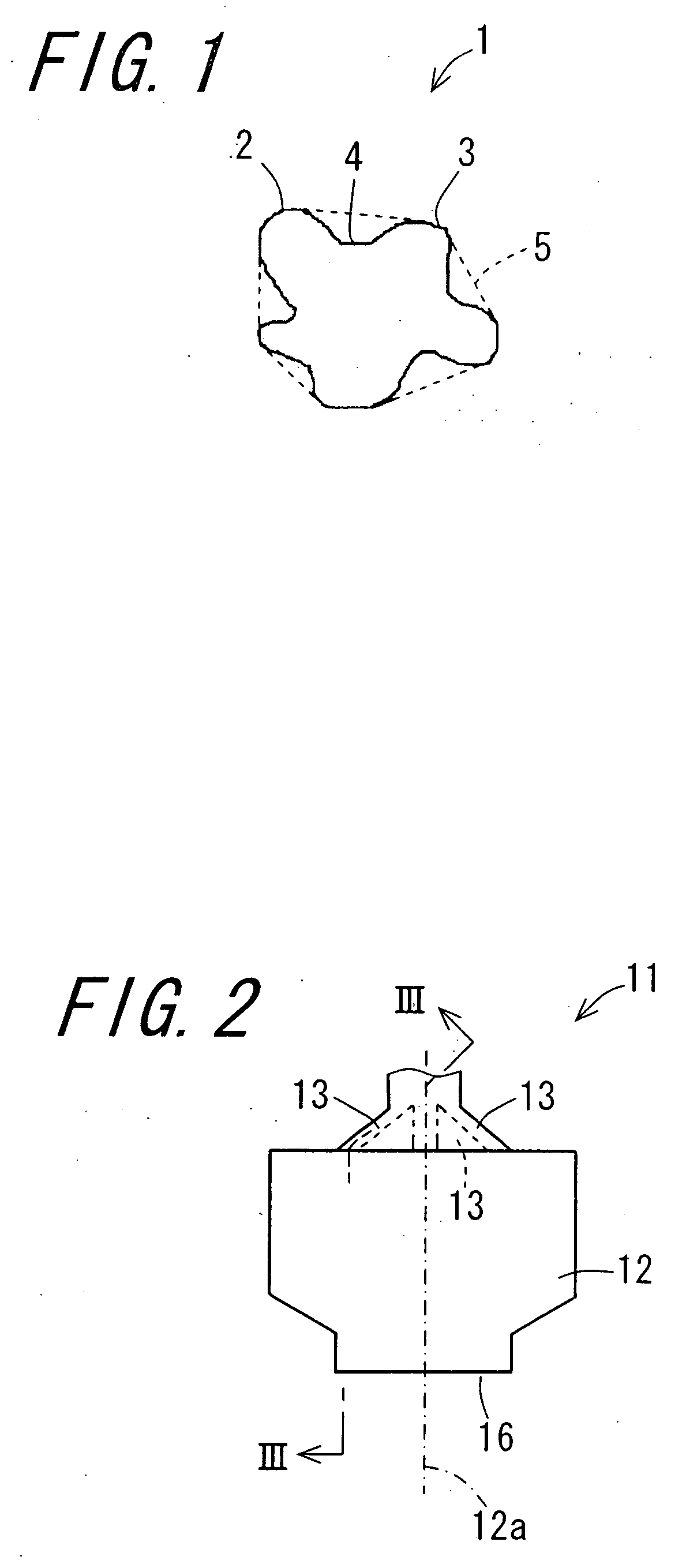
[0016] According to the invention, a relation is favorably set between a circumference length L1 of a projection image of toner particles containing binder resin and a colorant and a length L2 of envelope of the projection image of the toner particles. To be specific, a value determined by [(L1−L2) / L2]×100 is in a range of from 2.0 to 3.0. In the following description, the value determined by [(L1−L2) / L2]×100 will be referred to a toner envelope degree or an envelope degree of toner. A toner having a toner envelope degree of from 2.0 to 3.0 can swiftly come into contact at almost entire surfaces of toner particles with a regulating blade of a developing device and a carrier which is contained in developer in the case of using the toner in form of two-component developer. A rise of charging is therefore favorable after replenishment of the toner just stated. Accordingly, toner particles having a small charge amount are prevented from being generated even when a toner density of the developer is high. Furthermore, during a cleaning operation conducted by use of a cleaning unit, it is possible to prevent cleaning defects from appearing. Consequently, stable high-quality images exhibiting constant image densities can be formed without toner spattering or image fogs even in a color image for which a toner consumption is larger than that for a black-and-white image, or even in a high-humid environment where a charge amount tends to be small.
[0018] According to the invention, an average degree of circularity of the toner particles is 0.980 or less and therefore, as compared to a perfectly spherical toner, for example, the toner particles are more easily caught by a cleaning blade and thus more easily removed by the blade, with the result that the cleaning property will be further enhanced.
[0021] According to the invention, the electrophotographic developer is two-component electrophotographic developer which comprises the toner achieving the above effects and a carrier, with the result that an almost entire surface of the toner can come into contact with the carrier, thus exhibiting a favorable rise of charging after replenishment of the toner. This allows a quicker rise of charging and excellent cleaning property to appear, thus enabling formation of high-quality images having high definition and high density.
[0023] According to the invention, a relation is favorably set between a circumference length C1 of a projection image of the carrier and a length C2 of envelope of the projection image of the carrier. To be specific, a value determined by [(C1−C2) / C2]×100 is 3.0 or less. In the following description, the value determined by [(C1−C2) / C2]×100 will be referred to a carrier envelope degree. When the carrier envelope degree is 3.0 or less, a convex portion of the carrier can fit into a concave portion of the toner. Such a contact between the toner and the carrier at the concave portion of the toner can contribute to charging of the toner. This allows further enhancement in the charging property of the toner and a more favorable rise of charging after replenishment of the toner.
[0026] According to the invention, an image forming apparatus which forms an image with the toner achieving the above effects, with the result that a rise of charging is quick and excellent cleaning property appears, thus enabling formation of high-quality images whose definition and density are high.

Problems solved by technology

It is however difficult to stably form high-quality images by use of a toner which is merely decreased in particle diameter.
The toner is however deteriorated in the cleaning property since the shape of the toner close to the perfect sphere represented by 0.975 or more in the average degree of circularity will cause the toner to be less easily caught by a cleaning blade when removing the toner remaining on the photoreceptor drum.
The carrier disclosed in JP-A 2004-53947 is however unable to attain enhancement in the charging start-up property of the toner.

Method used


Image

  • Toner, developer, and image forming apparatus
  • Toner, developer, and image forming apparatus
  • Toner, developer, and image forming apparatus

Examples


example 1

[0184] A toner raw material was mixed for 10 minutes by a Henschel mixer: FM mixer (trade name) manufactured by Mitsui Mining Co. The toner row material contained, as indicated by combination ratios (part by weight), 83 parts by weight of polyester which serves as binder resin Tafton TTR-5 (trade name) manufactured by Kao Corporation, having a glass transition temperature (Tg) of 60° C. and a softening temperature (Tm) of 100° C.; 12 parts by weight of master batch containing as a colorant 40% by weight of C.I. pigment red 57:1; 3 parts by weight of carnauba wax which serves as a release agent. Refined carnauba wax (trade name) manufactured by S. KATO & Co., having a melting temperature of 83° C.; and 2 parts by weight of alkyl salicylate metal salt which serves as a charge control agent: Bontron E-84 (trade name) manufactured by Orient Co., Ltd.

[0185] A thus-obtained admixture of raw material was melt-kneaded by Kneadics MOS140-800 (trade name) manufactured by Mitsui Mining Co. an...

example 2

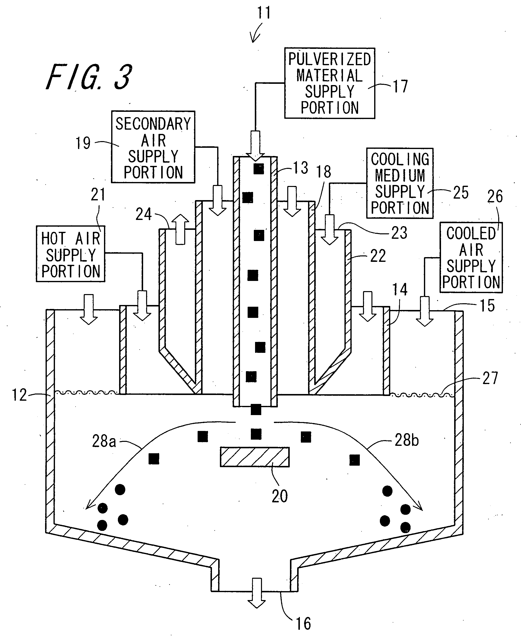
[0188] A toner of Example 2 was obtained in the same manner as Example 1 except that a device: Kryptron KTM-X type (trade name) manufactured by Earth Technica Co., Ltd., equivalent to the impact-type spheronizing device shown in FIG. 6, was used to form into the spherical shape the pulverized material of resin composition obtained in the same manner as Example 1. In the impact-type spheronizing device, an input amount of the pulverized material was set at 45 kg per hour, a rotation speed of a dispersing rotor 13,000 rpm, and a clearance d3 between the dispersing rotor and a stator 2.0 mm. A temperature of gas which was discharged together with the toner particles from a toner particle outlet, was 35° C. that was equal to or lower than the glass transition temperature of the binder resin.

example 3

[0189] A toner of Example 3 was obtained in the same manner as Example 1 except that a device: Faculty F-600 type (trade name) manufactured by Hosokawa Micron Corporation, equivalent to the impact-type spheronizing device shown in FIG. 4, was used to form into the spherical shape the pulverized material of resin composition obtained in the same manner as Example 1 and that no classification was carried out. In the impact-type spheronizing device, an input amount of the pulverized material was set at 4 kg for one time, and fine particles were removed under the condition that a rotation speed of a classifying rotor was set at 5,000 rpm, while cooled air flowing from a cooled air inlet into a treatment tank was set at 4° C., and the spheronization process was carried out for two minutes (120 seconds) under the condition that a rotation speed of a dispersing rotor was set at 5,800 rpm. A temperature of gas which was discharged together with the fine particles from a fine particle outlet...


PUM


Abstract

There is provided a toner which exhibits a quick rise of charging and excellent cleaning property and which can form high-quality images having high definition and high density. A toner envelope degree of the toner falls in a range of from 2.0 to 3.0, which degree is obtained by calculation of [(L1−L2) / L2]×100 wherein L1 represents a circumference length of a projection image of toner particles containing binder resin and a colorant, and L2 represents a length of envelope of the projection image of the toner particles.

Description

CROSS-REFERENCE TO RELATED APPLICATION [0001] This application claims priority to Japanese Patent Application No. 2006-250116, which was filed on Sep. 14, 2006, the contents of which are incorporated herein by reference in its entirety. BACKGROUND OF THE INVENTION [0002] 1. Field of the Invention [0003] The present invention relates to a toner, a developer, and an image forming apparatus. [0004] 2. Description of the Related Art [0005] Electrophotographic image forming apparatuses have been widely used as copiers so far, and in recent days, also as printers, facsimile machines, and the like equipments along with spread of computers since the electrophotographic image forming apparatuses operate excellently as output units for computer images created by computers. In a general electrophotographic image forming apparatus, a desired image is formed on a recording medium through a charging step, an exposing step, a developing step, a transferring step, a fixing step, and a cleaning step...

Claims


Application Information

Patent Timeline
IPC IPC(8): G03G9/08
CPCG03G9/0819G03G9/0827G03G9/113G03G9/107G03G9/10G03G9/108
Inventor ONDA, HIROSHIYAMAMOTO, YOSHINORISUZUKI, MASAO
Owner SHARP KK
Learn More