
Non-ambipolar radio-frequency plasma electron source and systems and methods for generating electron beams

a radio-frequency plasma and electron beam technology, applied in the field of systems, methods and devices for generating electron beams, can solve the problems of negatively charged spacecraft/satellite itself, negative charge of positively charged ion beams, and inability to provide the thrust to appropriately maneuver satellites or spacecrafts, etc., to eliminate the capacitance coupling effect of electric fields

Active Publication Date: 2008-03-20
WISCONSIN ALUMNI RES FOUND
View PDF34 Cites 40 Cited by
  • Summary
  • Abstract
  • Description
  • Claims
  • Application Information

AI Technical Summary

Benefits of technology

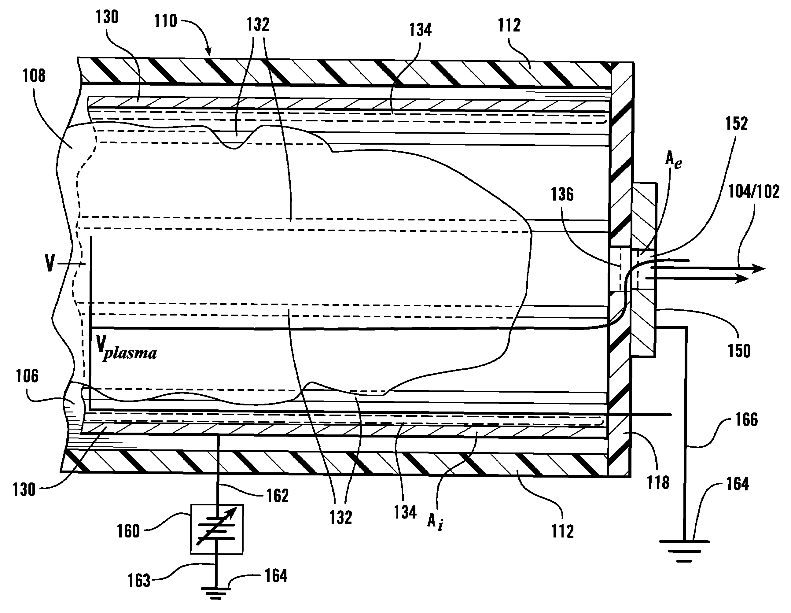
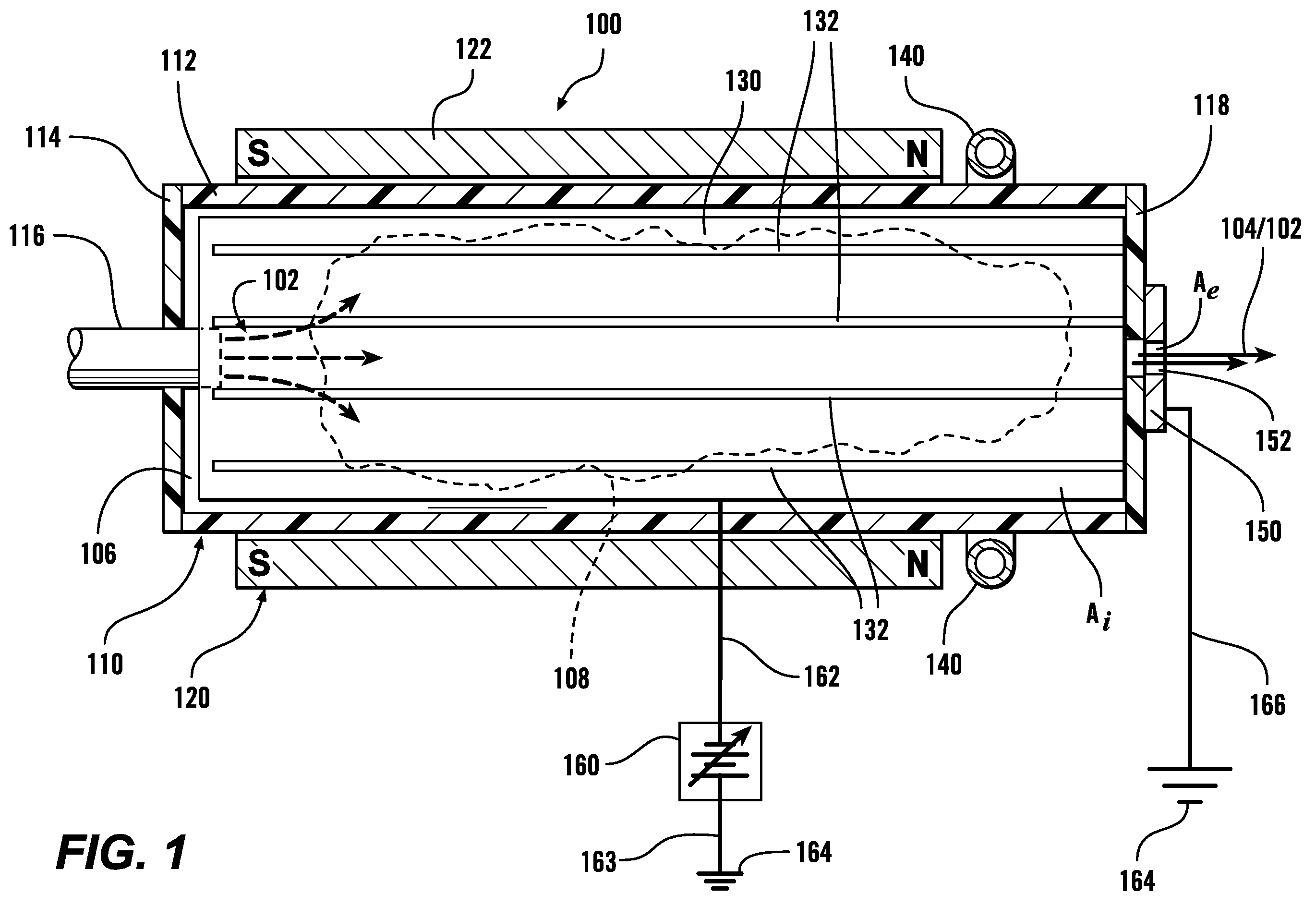
[0022]In various exemplary embodiments, an antenna located outside of the negatively-biased conducting surface generates a varying RF electromagnetic field around the electron beam generating device. The antenna can be capacitively coupled to the plasma, inductively driving currents in the plasma or inductively exciting helicon waves, provided in the negatively-biased conducting cylinder depending on the structure of the device and the plasma density. In various exemplary embodiments, slots or other voids in a negatively-biased conducting cylinder to allow the time-varying magnetic fields provided by the antenna to extend into the interior of the negatively-biased conducting cylinder to inductively couple to the gas within the negatively-biased conducting cylinder. In various exemplary embodiments, the negatively-biased conducting cylinder acts as Faraday shield to reduce, and possibly eliminate, any capacitive coupling of electric fields between the antenna and the plasma. In various exemplary embodiments, a simple antenna is used In various other exemplary embodiments, the antenna is configured to allow inductive or helicon coupling to the plasma.

Problems solved by technology

However, due to space-charge limitations within the ion beams, the charged ions in the ion beams tend not to stay tightly packed in the beam.
For example, in the spacecraft / satellite embodiments, if the beam remains positively-charged, two problems arise.
First, the spacecraft / satellite itself becomes negatively charged when the positive charge is emitted.
Second, because the ion beam is positively charged, it becomes attracted to the negatively-charged spacecraft / satellite, and thus does not travel in a straight line away from the spacecraft or satellite, or, in a worst-case leave the spacecraft environment at all.
As a result, a positively-charged ion beam does not provide the proper thrust to appropriately maneuver the satellite or spacecraft.

Method used


Image

  • Non-ambipolar radio-frequency plasma electron source and systems and methods for generating electron beams
  • Non-ambipolar radio-frequency plasma electron source and systems and methods for generating electron beams
  • Non-ambipolar radio-frequency plasma electron source and systems and methods for generating electron beams

Examples


Embodiment Construction

[0010]Conventionally, electron beams associated with spacecraft are generated by hollow cathodes. However, hollow cathodes are problematic for a number of reasons. First, as the hollow cathodes are used to generate the desired electron beam, they are slowly consumed. Typical maximum lifetimes for commercial hollow electrodes are on the order of only three to four years. Additionally, the present generation of hollow cathodes employ barium oxide-tungsten (BaO—W) inserts as their emitting surface. However, this emitting surface deteriorates over time. Once the hollow cathode becomes inoperable, it is no longer possible to use the electron generating device. Additionally, hollow cathodes are difficult to ignite, either initially or if they should go out during use, and can become contaminated, thus reducing their efficiency.

[0011]One proposed solution for this limited lifetime is to provide multiple hollow-cathode electron generating devices and / or to provide multiple hollow cathodes w...


PUM


Abstract

An electron generating device extracts electrons, through an electron sheath, from plasma produced using RF fields. The electron sheath is located near a grounded ring at one end of a negatively biased conducting surface, which is normally a cylinder. Extracted electrons pass through the grounded ring in the presence of a steady state axial magnetic field. Sufficiently large magnetic fields and / or RF power into the plasma allow for helicon plasma generation. The ion loss area is sufficiently large compared to the electron loss area to allow for total non-ambipolar extraction of all electrons leaving the plasma. Voids in the negatively-biased conducting surface allow the time-varying magnetic fields provided by the antenna to inductively couple to the plasma within the conducting surface. The conducting surface acts as a Faraday shield, which reduces any time-varying electric fields from entering the conductive surface, i.e. blocks capacitive coupling between the antenna and the plasma.

Description

[0001]The subject matter of this application was made with U.S. Government support awarded by the following agencies: NASA Glenn Research Center, Grant NNC04GA82G and U.S. Department of Energy, Grant DEFG0297ER54437. The United States has certain rights in this invention.BACKGROUND OF THE INVENTION[0002]1. Field of the Invention[0003]This invention is directed to systems, methods and devices for generating an electron beam.[0004]2. Related Art[0005]Electron beam sources are widely used in a variety of applications. Electron beam generators are used both as sources for the electron beams themselves, as charge neutralizers for charged ion beams, to produce protective thermal spacecraft coatings, to form plasma-assisted thin films, and to deposit optical coatings, such as, for example, for large mirrors, in forming metallized packaging films and in electron beam evaporation, electron beam surface modification, thin film growth, plasma-assisted chemical vapor deposition, plasma vapor de...

Claims


Application Information

Patent Timeline
Patent Type & Authority Applications(United States)
IPC IPC(8): H01J37/077
CPCF03H1/0025H01J2237/31H01J37/077H01J3/025H05H1/54
Inventor HERSHKOWITZ, NOAHLONGMIER, BENJAMINBAALRUD, SCOTT
Owner WISCONSIN ALUMNI RES FOUND
Learn More