
Electrophotographic photoconductor and method of preparing same

a photoconductor and electrochemical technology, applied in the field of electrochemical photoconductor, can solve the problems of reducing the charge potential and light sensitivity, increasing the background stains, and deteriorating image quality

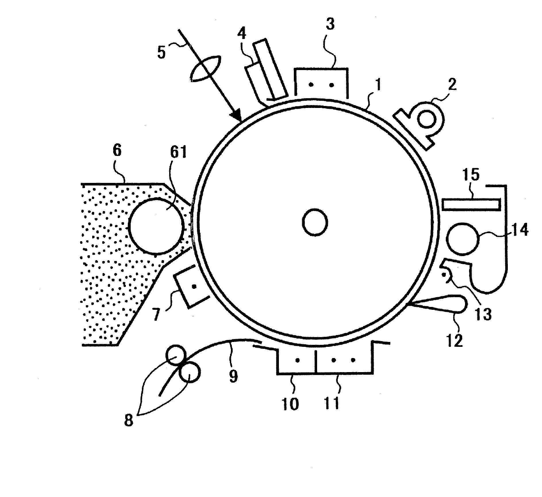
Inactive Publication Date: 2008-03-13
RICOH KK
View PDF12 Cites 4 Cited by
  • Summary
  • Abstract
  • Description
  • Claims
  • Application Information

AI Technical Summary

Benefits of technology

The solution provides a photoconductor with improved wear resistance, reduced residual potential variation, and enhanced durability, ensuring high-quality images over a longer period without significant surface degradation or image defects.

Problems solved by technology

In general, the organic electrophotographic photoconductors have drawbacks because the surface thereof is apt to be abraded upon repeated use, which causes a reduction of the charge potential and the light sensitivity thereof as well as injuries of the surface thereof, resulting in deterioration of the image quality such as an increase of background stains and a reduction of image density.
For this reason, it is one of the important problems to provide an electrophotographic photoconductor having high durability.
The organic electrophotographic photoconductors have additional drawbacks because cracks are apt to form when foreign matters such as lipids derived from human hands deposit on a surface thereof and when crystallization of the photoconductive material occurs on the deposited area.
However, the fluorine-modified silicone oil tends to be lost during repeated use and fails to maintain its effect for a long time.
The use of the filler, however, adversely affects the charging potential and residual potential and causes a problem that the potential greatly varies upon repeated use of the photoconductor.
H09-190004, however, has a problem that it is difficult to synthesize and purify the organic silicon-modified positive hole transporting compound.
An unpurified product causes a reduction in layer strength and adversely affects the electrophotographic properties.
The photoconductor of Japanese Laid-Open Patent Publication No. 2000-171990 has drawbacks that the charge transporting compound having incorporated thereinto a reactive group has poor compatibility and the mechanical strength of a layer obtained therefrom are not satisfactory.
In the case of the photoconductor of Japanese Laid-Open Patent Publication No. 2000-206715, the residual chain-polymerizable groups adversely affect the resistance to gases and the mechanical strengths of a layer obtained therefrom.

Method used


Image

  • Electrophotographic photoconductor and method of preparing same
  • Electrophotographic photoconductor and method of preparing same
  • Electrophotographic photoconductor and method of preparing same

Examples


synthesis example 1

Synthesis of Epoxy Group-Containing Amine Compound

[0131] In a reactor equipped with a stirrer, a thermometer, a dropping funnel and a reflux condenser provided with a trap to remove water formed during the reaction, 19.34 g (40.0 mmol) of 4-[2,2-bis(4-hydroxyphenyl)vinyl]phenyl-bis(4-methylphenyl)amine and 37.01 g (400.0 mmol) of epichlorohydrin are charged. The mixture was heated to 110° C. with stirring under a nitrogen gas stream. Then, while maintaining the mixture in the reactor at 100 to 120° C., 19.20 g (96.0 mmol) of a 10% by weight aqueous solution of sodium hydroxide were added dropwise to the mixture through 3 hours. During the reaction, epichlorohydrin emitted overhead from the reactor was condensed and returned to the reactor, while water was trapped and discharged from the system. After the addition of the sodium hydroxide solution had been completed, the reaction mixture was further reacted for 1 hour at 110° C. The resulting reaction mixture was allowed to cool to r...

example 1

[0134] An undercoat layer coating liquid, a charge generating layer coating liquid and a charge transporting layer coating liquid, which had the compositions shown below, were coated and dried one by one to overlay an undercoat layer of 3.5 μm thick, a charge generating layer of 0.2 μm thick and a charge transporting layer of 26 μm thick on an aluminum cylinder.

[0135] [Undercoat layer coating liquid]

Titanium oxide400 partsMelamine resin 40 partsAlkyd resin 60 parts2-Butanone500 parts

[0136] [Charge Generating Layer Coating Liquid]

Bisazo pigment of the formula shown below12partsPolyvinyl butyral resin5parts2-Butanone200partsTetrahydrofuran400parts

[0137] [Charge Transporting Layer Coating Liquid]

Polycarbonate resin10parts(Bisphenol Z-type polycarbonate resinmanufactured by Teijin Kasei Inc.)Charge transporting material10partshaving the formula shown belowTetrahydrofuran100parts1% Silicone oil tetrahydrofuran solution1part(KF50-100CS manufactured by Shin-etsuChemical Industry Co., Ltd....

example 2

[0140] A precursor liquid for a protective layer coating liquid having the following formulation was prepared:

[0141] [Precursor]

Methyltrimethoxysilane5partsPhenyltriethoxysilane5parts1% Aqueous acetic acid solution5.57partsTetrahydrofuran30.7partsn-Butanol3.67parts

[0142] The precursor liquid was then heated at 60° C. for 2 hours with stirring for silanolizing the methyltrimethoxysilane and phenyltriethoxysilane by hydrolysis. The resulting liquid was mixed with 4.2 parts of the epoxy group-containing amine compound obtained in Synthesis Example 1 above to obtain a protective layer coating liquid (II). An electrophotographic photoconductor was then prepared in the same manner as that in Example 1 except that the protective layer coating liquid (II) was substituted for the protective layer coating liquid (I).


PUM

PropertyMeasurementUnit
temperatureaaaaaaaaaa
particle diameteraaaaaaaaaa

Abstract

An electrophotographic photoconductor having a layer of a crosslinked resin obtained by reacting an epoxy group-containing amine compound having a charge transferability-imparting group with at least one silicon compound selected from an epoxy ring-free alkoxysilane compound, an epoxy ring-free silanol compound, an epoxy ring-containing alkoxysilane compound and an epoxy ring-containing silanol compound.

Description

REFERENCE TO PRIOR APPLICATIONS [0001] This application is a Divisional of U.S. application Ser. No. 10 / 458,626, filed on Jun. 11, 2003, now allowed. This application claims priority to Japanese Patent Application Nos. 2002-171954, filed Jun. 12, 2002; 2002-171921, filed Jun. 12, 2002; 2003-003709, filed Jan. 9, 2003; 2003-016661, filed Jan. 24, 2003.BACKGROUND OF THE INVENTION [0002] 1. Field of the Invention [0003] This invention relates to an electrophotographic photoconductor for use in image forming machines such as printers, copying machines and facsimile machines. The present invention is also directed to a method of preparing an electrophotographic photoconductor. [0004] 2. Description of the Related Art [0005] Recent development of information processing systems using electrophotography is striking. In particular, laser printers and digital copying machines in which information is recorded using light as digital signals have shown significant improvement in image quality an...

Claims


Application Information

Patent Timeline
Patent Type & Authority Applications(United States)
IPC IPC(8): G03G15/02G03G5/05G03G5/147
CPCG03G5/0557G03G5/0575G03G5/0578G03G5/14795G03G5/0596G03G5/14747G03G5/14791G03G5/0592
Inventor NAGAI, KAZUKIYOTANAKA, CHIAKISUZUKI, TETSUROIKUNO, HIROSHILI, HONGGUO
Owner RICOH KK
Learn More