Eureka AIR delivers breakthrough ideas for toughest innovation challenges, trusted by R&D personnel around the world.

Buffer allocation method for multi-class traffic with dynamic spare buffering

a buffer allocation and multi-class technology, applied in data switching networks, frequency-division multiplexes, instruments, etc., can solve the problems of increasing system load, limited buffer size, and node being able to output data packets at a rate sufficient to keep up, so as to improve the buffering method

Inactive Publication Date: 2008-03-13
IBM CORP
View PDF18 Cites 32 Cited by
  • Summary
  • Abstract
  • Description
  • Claims
  • Application Information

AI Technical Summary

Benefits of technology

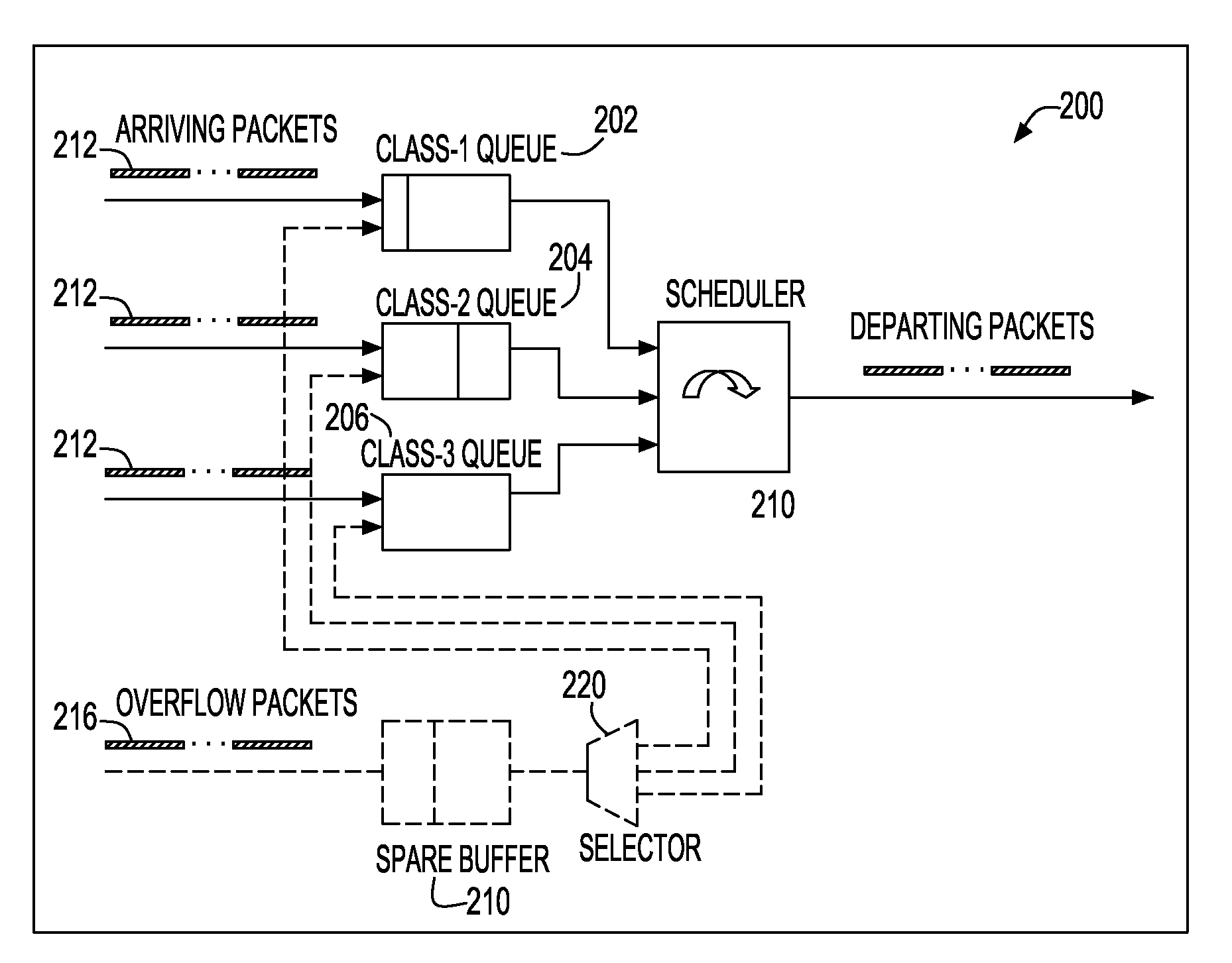
[0011]Another object of the invention is to provide a dynamic spare buffering method for support of multi-class traffic, which avoids requiring large queues in the presence of unpredictable traffic patterns.

Problems solved by technology

Depending on the amount and nature of the data packets entering a network node, it is possible that the node will not be able to output the data packets at a rate sufficient to keep up with the rate that the data packets are received.
However, one problem with this solution is that it may be desirable to give different types of data packets different priorities.
However, if the data packets are carrying data for a high-speed computer application, the loss of even one data packet may corrupt the data resulting in a severe problem.
However, switches / routers have fixed amount of memory (DRAM) and therefore their buffers have limited size.
As the link capacity increases, for example from 1 Gbit / sec to 10 Gbit / sec, effective buffer management becomes even more imperative as significantly large buffers will have a major cost increase on the system.
The cost impact of large buffers is even more significant when the system has to support multiple traffic classes for diversified user traffic in order to provide different classes of QoS (Quality of Service).
However, due to the unpredictability nature of traffic patterns, it is not feasible to accurately size each queue class.
Therefore in time of congestion, some queues overflow and as a result packet loss occurs.

Method used


Image

  • Buffer allocation method for multi-class traffic with dynamic spare buffering
  • Buffer allocation method for multi-class traffic with dynamic spare buffering
  • Buffer allocation method for multi-class traffic with dynamic spare buffering

Examples


Embodiment Construction

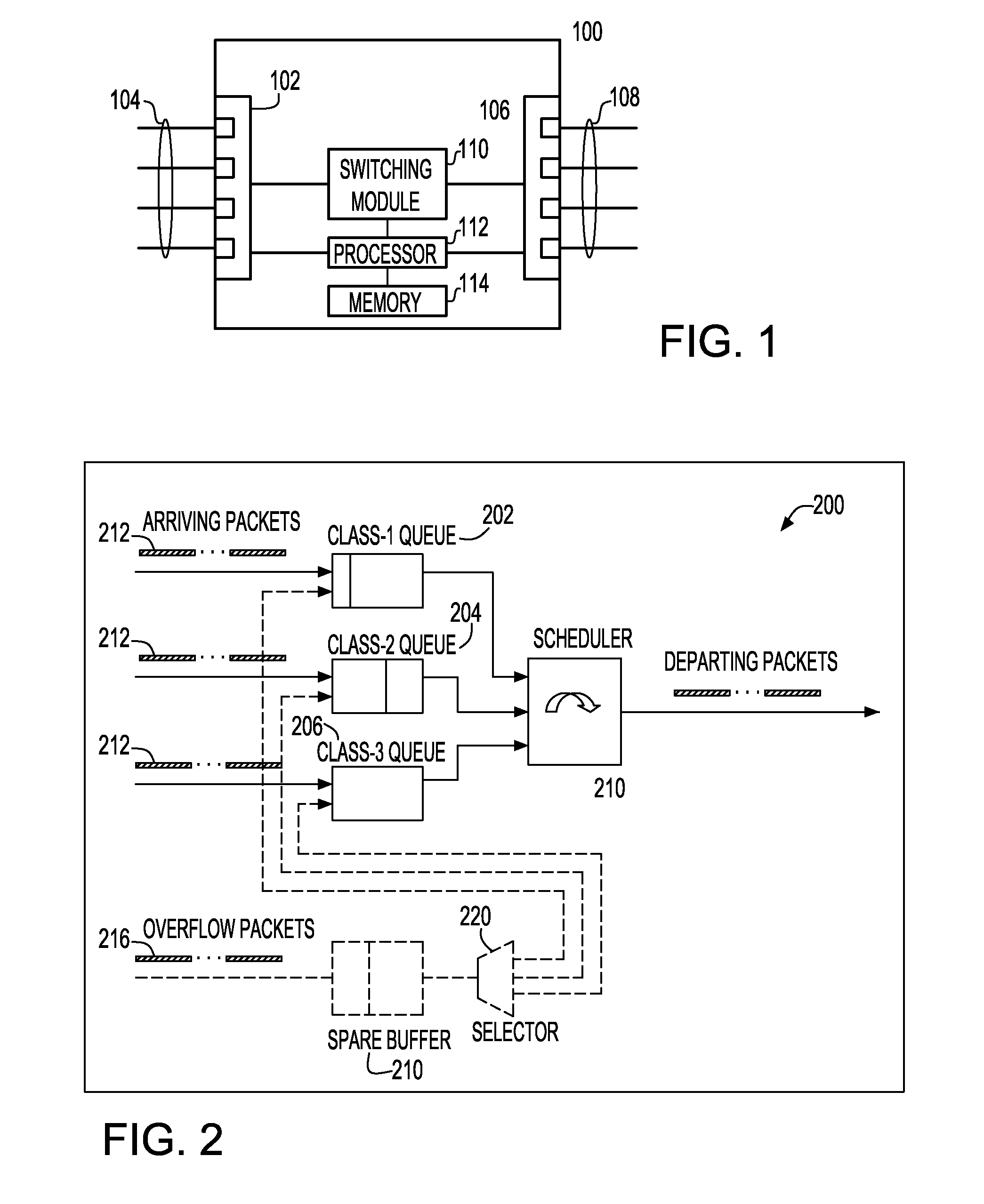
[0018]FIG. 1 shows a block diagram of a network node 100 in which the present invention may be utilized. Network node 100 includes input ports 102 for receiving data packets from input links 104. Network node 100 also includes output ports 106 for transmitting data packets on output links 108. Switching module 110 is connected to input ports 102 and output ports 106 for switching data packets received on any input link 104 to any output link 108. A processor 112 is connected to a memory unit 114, input ports 102, switching module 110, and output ports 106. The processor controls the overall functioning of the network node 100 by executing computer program instructions stored in memory 114. Although memory 114 is shown in FIG. 1 as a single element, memory 114 maybe made up of several memory units. Further, memory 114 may be made up of different types of memory, such as random access memory (RAM), read-only memory (ROM), magnetic disk storage, optical disk storage, or any other type ...


PUM


Abstract

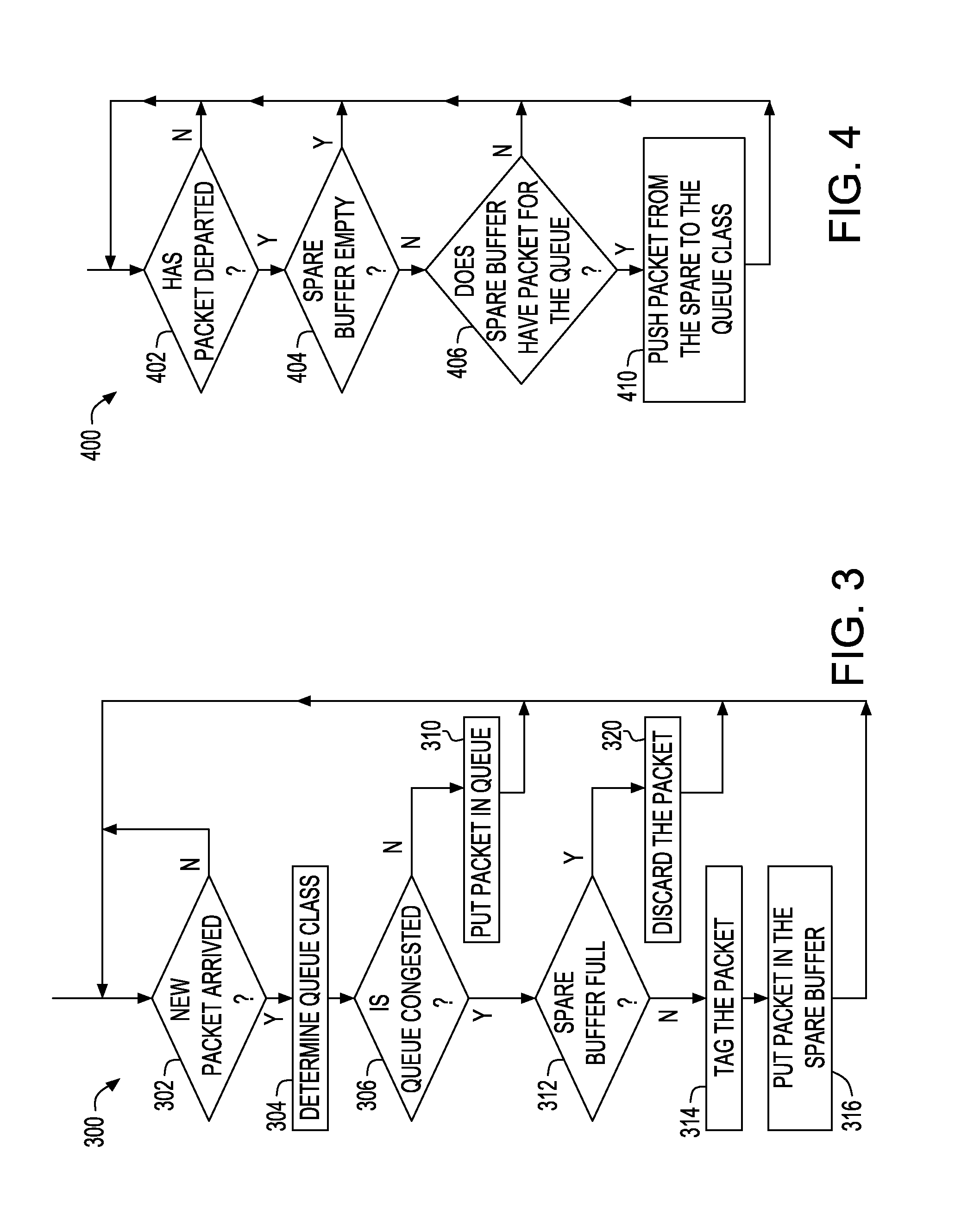
Disclosed are a method of and system for allocating a buffer. The method comprises the steps of partitioning less than the total buffer storage capacity to a plurality of queue classes, allocating the remaining buffer storage as a spare buffer, and assigning incoming packets into said queue classes based on the packet type. When a queue becomes congested, incoming packets are tagged with the assigned queue class and these additional incoming packets are sent to said spare buffer. When the congested queue class has space available, the additional incoming packets in said spare buffer are pushed into the tail of the congested queue class.

Description

BACKGROUND OF THE INVENTION[0001]1. Field of the Invention[0002]This invention generally relates to shared memory buffer management in network nodes. More specifically, the invention relates to the use of dynamic spare buffering for multi-class network traffic.[0003]2. Background Art[0004]Data networks are used to transmit information between two or more endpoints connected to the network. The data is transmitted in packets, with each packet containing a header describing, among other things, the source and destination of the data packet, and a body containing the actual data. The data can represent various forms of information, such as text, graphics, audio, or video.[0005]Data networks are generally made up of multiple network nodes connected by links. The data packets travel between endpoints by traversing the various nodes and links of the network. Thus, when a data packet enters a network node, the destination information in the header of the packet instructs the node as to the...

Claims


Application Information

Patent Timeline
IPC IPC(8): H04L12/26H04L12/56
CPCH04L47/10H04L47/11H04L47/12H04L49/9078H04L47/30H04L49/90H04L49/9057H04L47/2441
Inventor HIMBERGER, KEVIN D.PEYRAVIAN, MOHAMMAD
Owner IBM CORP
Why Eureka
Eureka Blog
Learn More