Optical encoder
a technology of optical encoder and optical encoding, applied in the direction of optical conversion of sensor output, instruments, measurement devices, etc., can solve the problems of reduced sn ratio, reduced received light, deteriorating operation accuracy, etc., and achieve excellent operation accuracy and increase the operation accuracy of electronic equipment
- Summary
- Abstract
- Description
- Claims
- Application Information
AI Technical Summary
Benefits of technology
Problems solved by technology
Method used
Image

Examples
first embodiment
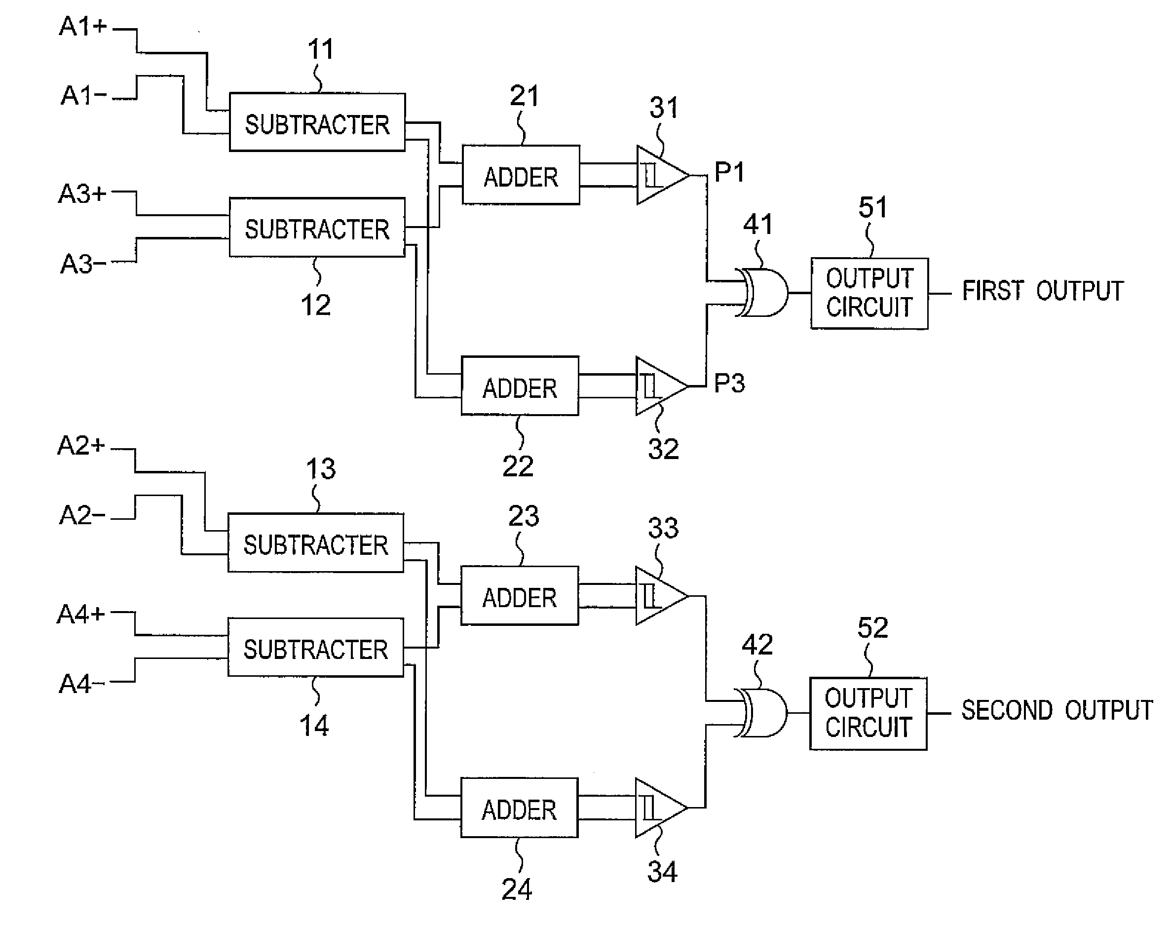
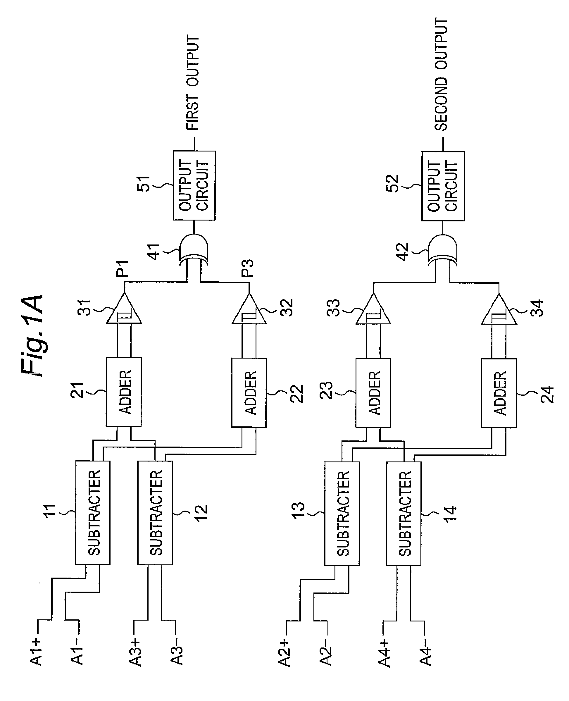
[0042]FIG. 1A is a representative block diagram of a light-receiving circuit included in a first embodiment of the optical encoder according to the present invention.
[0043]As shown in FIG. 1A, the light-receiving circuit constitutes a signal processing section and has subtracters 11 to 14 serving as the signal processing circuits, adders 21 to 24 serving as the arithmetic processing section, comparators 31 to 34 serving as the A / D converting section, exclusive-or circuits 41 and 42, and output circuits 51 and 52 as the digital signal section.
[0044]In FIG. 1A, A1+, A2+, A3+, A4+, A1−, A2−, A3−, and A4− are signals caused by photocurrents obtained from light-receiving elements, respectively, and are different in phase by 45 degrees.
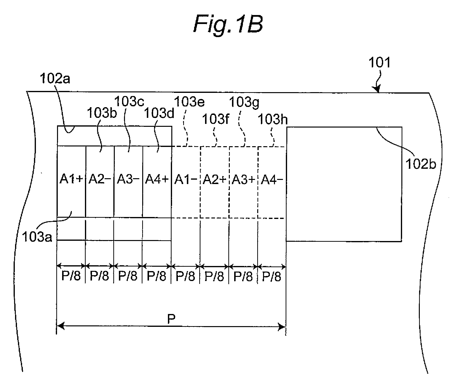
[0045]FIG. 1B shows an example of an optical system by which the signals A1+, A2+, A3+, A4+, A1−, A2−, A3−, and A4− are obtained. The example shown in FIG. 1B has a movable member 101, eight photodiodes 103a to 103h for signal production serving as the ligh...
second embodiment
[0055]Next, a second embodiment of the optical encoder according to the present invention will be described with reference to FIGS. 3A and 3B. The second embodiment is different from the first embodiment in that the second embodiment has subtracters 111 to 114 having no adjustable resistor and adders 221 and 222 having adjustable resistors R31 and R34. For this reason, in the second embodiment, only points which are different from the first embodiment will be mainly described. L1 to L6 in FIG. 3A are connected to M1 to M6 in FIG. 3B, respectively.
[0056]In the second embodiment, as is apparent from FIG. 3A, the subtracters 111 and 112 corresponding to the subtracters 11 and 12 of the first embodiment have no adjustable resistor. Although the subtracters 11 and 12 of the first embodiment take out the output signals of the differential amplifiers as voltages using resistors, the subtracters 111 and 112 of the second embodiment have no adjustable resistor. Furthermore, the two remaining...
third embodiment
[0063]Next, a third embodiment of the optical encoder according to the present invention will be described with reference to FIGS. 4A and 4B. The third embodiment is different from the second embodiment in that the third embodiment has subtracters 311 and 312 and adders 321 and 322 instead of the subtracters 111 and 112 and the adders 221 and 222 shown in FIGS. 3A and 3B. For this reason, in the third embodiment, only points which are different from the second embodiment will be mainly described. L11 to L16 in FIG. 4A are connected to M11 to M16 in FIG. 4B, respectively.
[0064]As shown in FIG. 4A, in the subtracter 311, resistors R41 and R42 are connected with the emitters of the transistors Tr31 and Tr32 of a current mirror circuit, and the resistor R42 is an adjustable resistor the resistance value of which is adjustable. Furthermore, in the subtracter 312, resistors R43 and R44 are connected with the emitters of the transistors Tr33 and Tr34 of a current mirror circuit.
[0065]On th...
PUM
 Abstract
Description
Claims
Application Information
 - R&D
- Intellectual Property
- Life Sciences
- Materials
- Tech Scout
- Unparalleled Data Quality
- Higher Quality Content
- 60% Fewer Hallucinations
Browse by: Latest US Patents, China's latest patents, Technical Efficacy Thesaurus, Application Domain, Technology Topic, Popular Technical Reports.
© 2025 PatSnap. All rights reserved.Legal|Privacy policy|Modern Slavery Act Transparency Statement|Sitemap|About US| Contact US: help@patsnap.com