
Apparatus for gravitation-compensated mounting of a measurement object

Inactive Publication Date: 2008-02-28
CARL ZEISS OPTRONICS
View PDF5 Cites 0 Cited by
  • Summary
  • Abstract
  • Description
  • Claims
  • Application Information

AI Technical Summary

Benefits of technology

[0006]The object of the present invention is to provide an apparatus for gravitation-compensated mounting of a measurement object, which ensures stable and precise mounting of the measurement object with little hardware complexity.
[0010]By way of example, a measurement object of about 200×100×0.5 mm and a natural weight of about 25 g can be supported by approximately 20 such supporting elements with adequate stability and precision.
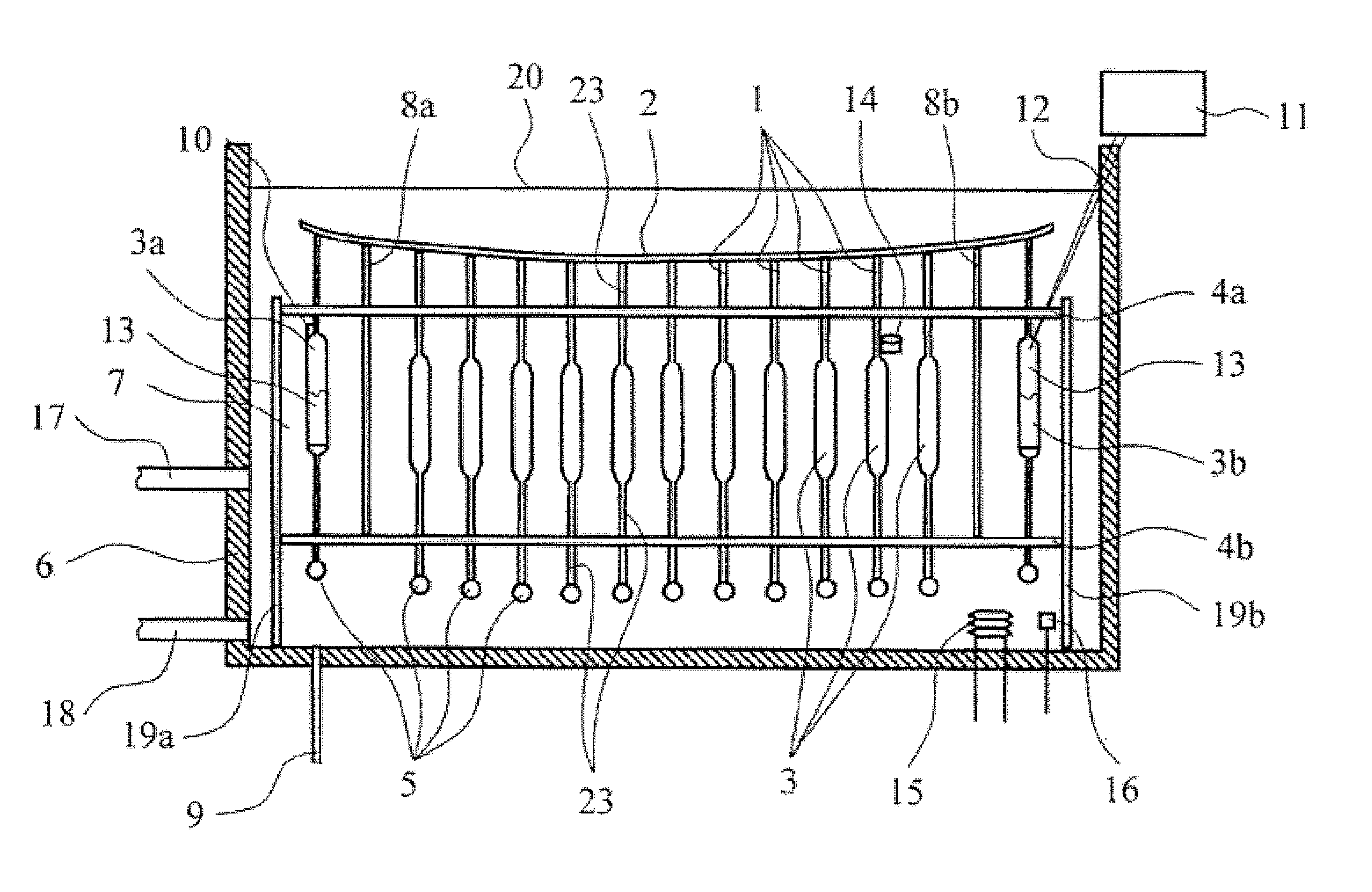
[0015]One alternative to this is to design the floating bodies which, for example, are in the form of hollow glass bodies, to be open at the bottom, with the internal cavity in the glass bodies to be at least partially filled with a buoyant medium whose density is less than that of the surrounding carrier liquid. An oil, gas or a solid may be used, for example, for the buoyant medium in this case, with water being used for the carrier liquid. This variant of the invention provides a particularly simple capability of matching the resultant supporting force.
[0016]In a first alternative, fine adjustment can be carried out by means of the amount of buoyant medium in the hollow glass body. For this purpose, for example, oil can be deliberately introduced into the cavities which are open at the bottom via an opening at the bottom of the reservoir in which the apparatus is located. In order to reduce the resultant supporting force, the oil can be let out through an opening at the top of the hollow glass body. The water which flows back into the cavity in this case reduces the volume of the water displaced by the hollow floating bodies and therefore reduces the buoyancy force exerted by the floating body. In this case, it is also feasible to equip the glass body with two cavities, one of which is closed and contains a gas, e.g. air, and in this way provides the majority of the required buoyancy, with the second cavity being formed by the cavity that is open at the bottom as already described, and which allows fine adjustment of the resultant supporting force by means of the oil level in it.

Problems solved by technology

Particularly for measurement objects such as these, the effect of gravitation must be particularly effectively precluded during measurement and quality control.

Method used


Image

  • Apparatus for gravitation-compensated mounting of a measurement object
  • Apparatus for gravitation-compensated mounting of a measurement object
  • Apparatus for gravitation-compensated mounting of a measurement object

Examples


Embodiment Construction

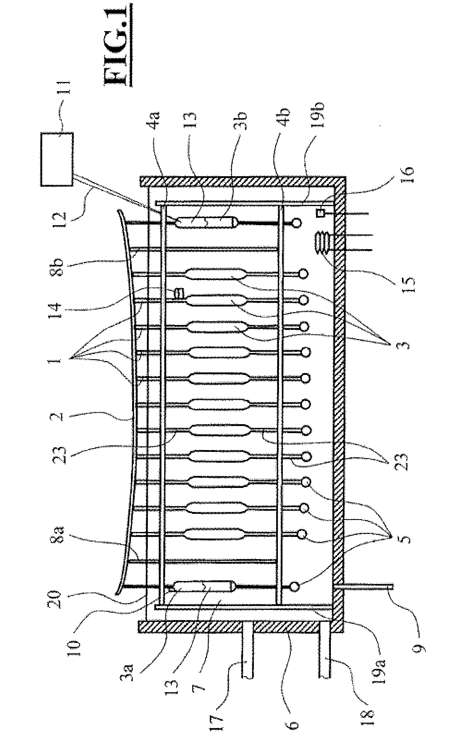
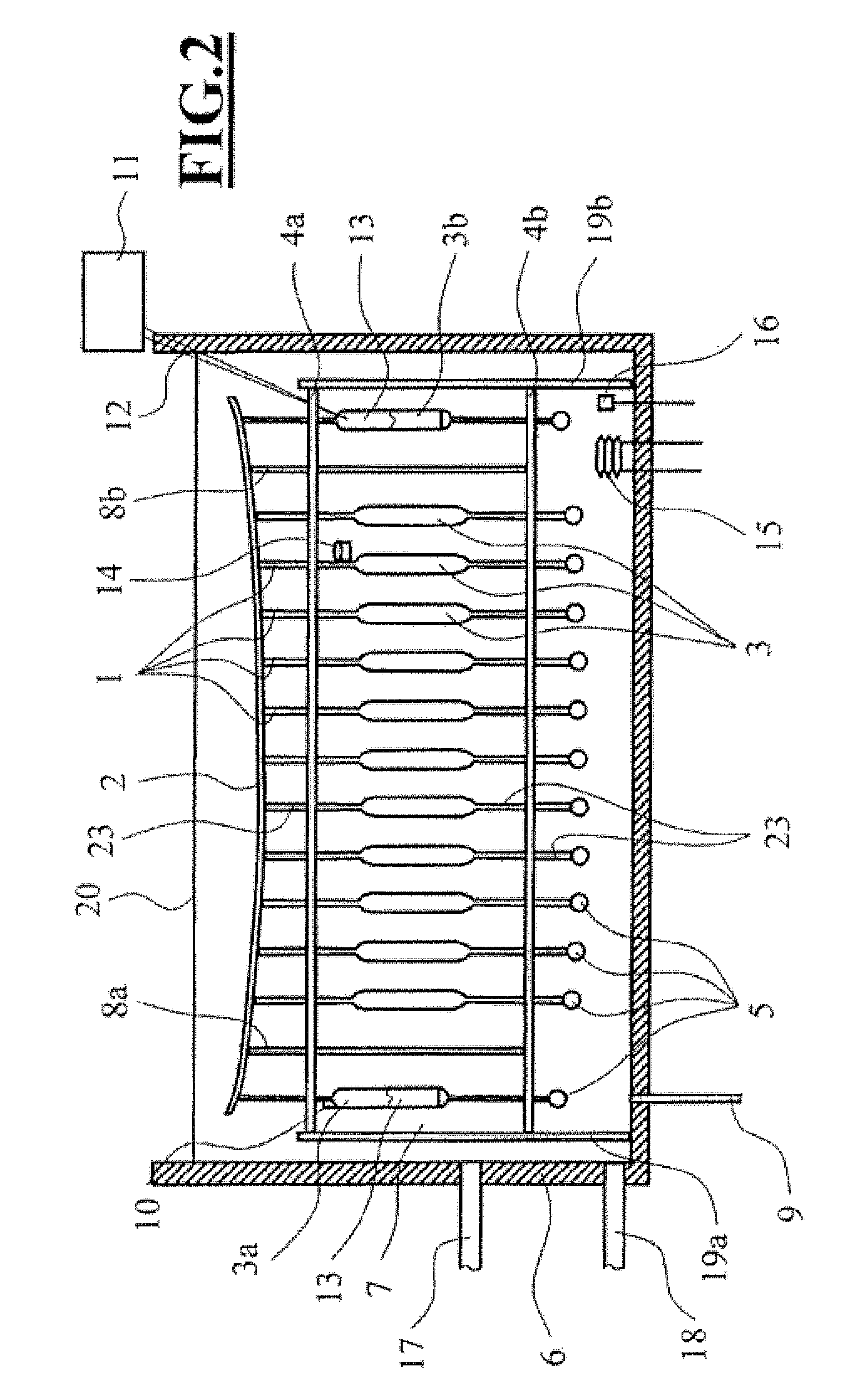
[0025]The cross section, in the form of a sketch, as illustrated in FIG. 1 through the arrangement according to the invention shows a measurement object 2 mounted on a large number of floating supporting elements 1. The floating supporting elements 1 in this case each have one floating body 3, and are adjusted to be in an approximately vertical position by means of the stationary guide plates 4a and 4b of the guide frame 22. A plurality of floating bodies 3 can also be provided for each supporting element 1, instead of one floating body 3. The guide plates 4a and 4b are arranged fixed to the basin via stand legs 19a to 19d. The fixed arrangement can be provided by means of gravity or fixing to the basin base or the basin wall.

[0026]Lead weights 5 are fitted, such that they can be detached or are fixed, to the lower face of the supporting elements 1, for adaptation of the resultant supporting force. The entire arrangement is located in the basin 6, which is filled with a carrier liqu...


PUM


Abstract

An apparatus is provided for gravitation-compensated mounting of a measurement object (2) having a plurality of supporting elements (1) which each act at at least one point on the measurement object (2), with the supporting elements (1) being designed such that they exert a constant force when small changes occur in the position of the measurement object (2). The supporting elements (1) are provided with floating bodies (3) arranged in a carrier liquid (7).

Description

CROSS REFERENCE TO RELATED APPLICATION[0001]This application related to and claims priority to corresponding German Patent Application No. 10 2006 039 820.3, which was filed on Aug. 25, 2006, and which is incorporated by reference herein.BACKGROUND OF THE INVENTION[0002]1. Field of the Invention[0003]The invention relates to an apparatus for gravitation-compensated mounting of measurement objects.[0004]2. Description of the Related Art[0005]Optical components which have a considerable extent have been used for several decades, in particular in astronomy. One continuous requirement for the production and in particular for the testing and measurement of such components is to find a reasonable compromise between the stiffness required for the components, which are normally manufactured with high precision, and a weight that is as low as possible. It is also desirable to find a possible way to mount these components in a stable and precise manner both when in use in the field and during...

Claims


Application Information

Patent Timeline
IPC IPC(8): G02B7/185
CPCG02B7/183G02B7/008
Inventor LENKE, RALF
Owner CARL ZEISS OPTRONICS
Learn More