
Method and apparatus for image processing

a technology of image identification and apparatus, applied in the field of apparatus and methods for image identification, can solve the problems of high cost, correspondingly high cost, and tedious learning processes, and achieve the effect of reducing the number of images

Inactive Publication Date: 2009-09-08
BAUMER OPTRONIC
View PDF3 Cites 3 Cited by
  • Summary
  • Abstract
  • Description
  • Claims
  • Application Information

AI Technical Summary

Benefits of technology

[0011]The selection process according to the invention, in which contour points which have the lowest connection probability to the central point are in each case sorted out from a set, offers the advantage of requiring very little memory. In particular, the processing can be carried out on the basis of continuous list data. The small amount of memory which is required for this purpose even allows processing in real time, with little complexity in terms of the hardware to be used. Furthermore, because of their simplicity, the processes described above can easily be implemented in hardware modules without complex software and peripheral circuitry. The apparatus according to the invention can thus be designed in a very simple form as a very compact integrated hardware image processing apparatus. In order to reduce the amount of memory required, further processing of the contour points in the form of continuous list data is, in particular, also particularly advantageous. This list data preferably includes only the pixel coordinates of relevant contour points as well as attributes for the surrounding area, and therefore only that data which is relevant for contour identification. The amount of data is in this way accordingly reduced to a minimum in comparison to the original data of the image. The aim of the sorting-out process is to determine those contour points which, together with the respective central point under consideration, belong to the same contour.
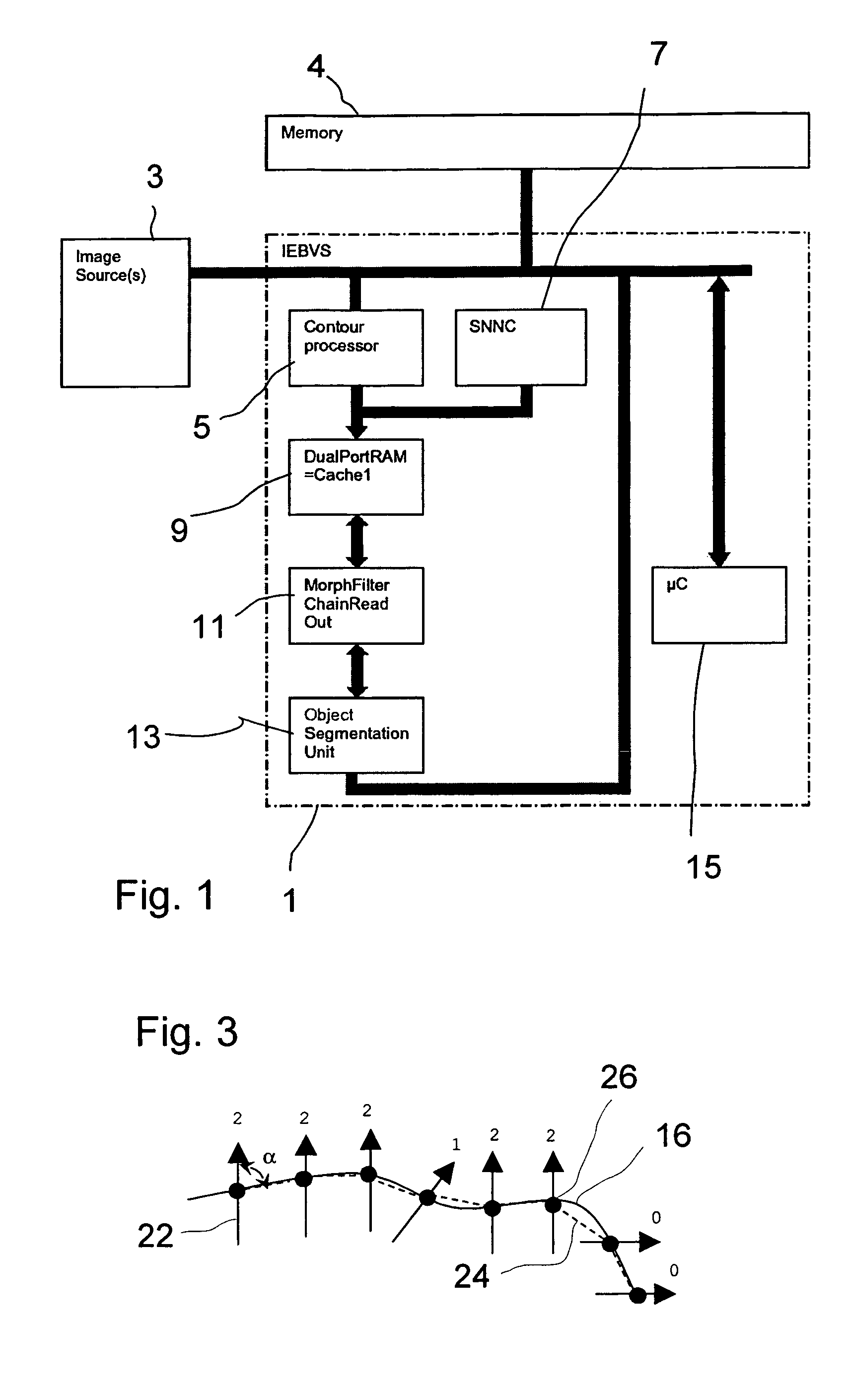
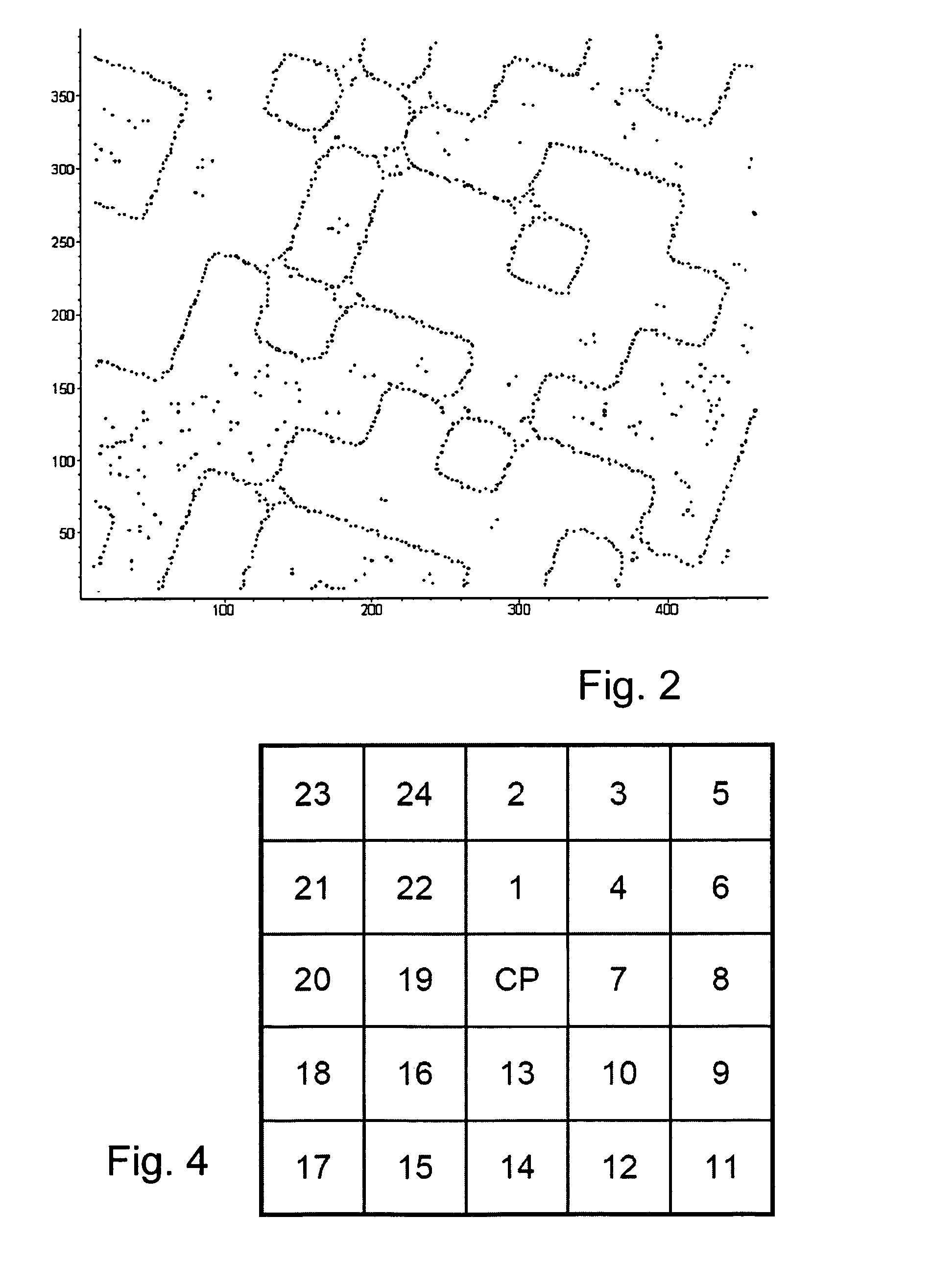
[0013]This selection process of the classifier can be carried out particularly effectively with a small number of computation operations and with little hardware complexity when one subset from the set of the contour points in the vicinity of the central point or of the contour points which are adjacent to the central point is in each case formed as a triple with the central point and two further contour points with the associated connection probabilities, and the lowest probability is determined, preferably by three comparators, for the connection probabilities and with that contour point which is adjacent to the central point and from which the link with the lowest connection probability within the triple originates being in each case sorted out from a neighborhood set of the contour points which are adjacent to the central point, provided that the associated link does not connect two contour points which are adjacent to the central contour point.
[0025]In order to allow the image data to be processed quickly with only a small amount of memory being required, in particular in order to determine contour points and connectors from the image data, it is also preferable for the image data to be read in a plurality of strips, which each have a width of more than 1 pixel, preferably at least 16 pixels, and particularly preferably 26 or 32 pixels. In this case, the image data is preferably read successively in strips which overlap by more than one pixel, preferably by at least 4 pixels, and particularly preferably by at least 8 pixels. This overlap will admittedly result in connectors in the overlap area being calculated twice in some circumstances, but this additional complexity is more than compensated for by the fact that the individual determined contours can be composed again more easily and with fewer errors.
[0035]It has been found that low-artifact determination of links between contour points operates even with a small area surrounding a selected central contour point. Links between contour points can thus be determined reliably when connection probabilities for possible links of contour points are in each case calculated only for those further contour points including the central contour point which are a maximum distance of 2 to 2.5 pixels away from a contour point with respect to the raster of the digital image.

Problems solved by technology

A procedure such as this is obviously highly complex and correspondingly expensive.
In addition, technical implementation in this case often also includes tedious learning processes, by means of which the system is trained to identify selected objects.
A further problem is that memory-intensive and complicated calculations are required for image identification.
Real-time identification is therefore virtually impossible to achieve in this way.

Method used


Image

  • Method and apparatus for image processing
  • Method and apparatus for image processing
  • Method and apparatus for image processing

Examples


Embodiment Construction

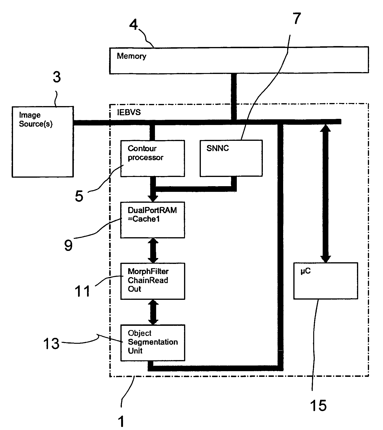
[0057]FIG. 1 shows the structure or architecture of an apparatus 1 according to the invention in the form of an integrated real-time image processing system IRTIPS. This IRTIPS comprises an image interface to which one or more image sources 3, for example CCD cameras, can be connected and which stores the image data as a digital image in an image memory 4. A contour point processor 5 in the form of an integrated hardware unit accesses this image memory 4 and is designed to scan the data of a digital image which is stored in the image memory 4, to determine contour points with subpixel accuracy, and to store this as continuous list data in a memory. The contour point processor 5 produces the coordinates and selected features of contour points in list form. Features are, for example, gray levels or colors of the adjacent regions, contrasts or directions.

[0058]The coordinates are output with subpixel accuracy within the “Regions of Interest”, for example of horizontally arranged strips...


PUM


Abstract

The methods and apparatuses determine contour points from image data and carried out a segmentation process on the basis of the contour points, during which associated contour points are combined to form objects for further processing.

Description

BACKGROUND OF THE INVENTION[0001]1. Field of the Invention[0002]The invention relates in general to apparatuses and methods for image processing. In particular, the invention relates to a method and an apparatus for image processing in which contour points are determined from the image data and a segmentation process is carried out on the basis of the contour points, during which associated contour points are combined to form objects for further processing.[0003]2. Description of Related Art[0004]Nowadays, image processing systems are used in order to achieve automatic object identification for widely different technical applications. By way of example, industrial robots are frequently oriented on the basis of processed image data, allowing a robot to identify an object and its orientation and position. In order to ensure reliable identification of objects, a large amount of “a priori” knowledge about the object to be identified has, however, been required until now. This often invo...

Claims


Application Information

Patent Timeline
IPC IPC(8): G06K9/46G06V10/46
CPCG06K9/48G06K9/4638G06V10/457G06V10/46
Inventor BEIKIRCH, LARSIHLEFELD, JOACHIMVIETZE, OLIVER
Owner BAUMER OPTRONIC
Learn More