
Context look ahead storage structures

a storage structure and context look ahead technology, applied in the field of data processing, can solve the problems of increasing routing delays, adversely affecting performance, increasing routing delays, etc., and achieve the effect of small and fast lower-level memory areas, without significantly affecting the accuracy of the structur

Inactive Publication Date: 2008-02-21
INT BUSINESS MASCH CORP
View PDF8 Cites 6 Cited by
  • Summary
  • Abstract
  • Description
  • Claims
  • Application Information

AI Technical Summary

Benefits of technology

[0015] As technology advances, routing delays are increasing. The demands of storing only the most important and relevant information in the critical area of the chip and moving the rest of the information to a secondary storage, located away from the critical high frequency area are needed for high performance. However, having bigger Meta-structures affects performance adversely by increasing the routing delays for other structures or processing elements.
[0016] As these structures become larger, the contrasting requirement of having a high hit rate as well as reduced access latency gives rise to arranging the structure hierarchically and prefetching from the bigger table to the smaller table. For effective prefetching, a scheme is provided that can identify the relevant information at the higher level and transfer the information ahead of its use to the first level.
[0019] A technique is described to prefetch branch and other Meta-information from a high level memory area to a lower-level memory area. The Meta-information is prefetched ahead in time of its normal use by the processor. This feature may be used to make the lower-level memory area small and fast, without impacting the accuracy of the structure significantly.

Problems solved by technology

As technology advances, routing delays are increasing.
However, having bigger Meta-structures affects performance adversely by increasing the routing delays for other structures or processing elements.
However, the table hardware needs to be packaged in the speed critical instruction fetch and branch prediction area of the machine.

Method used


Image

  • Context look ahead storage structures
  • Context look ahead storage structures
  • Context look ahead storage structures

Examples


Embodiment Construction

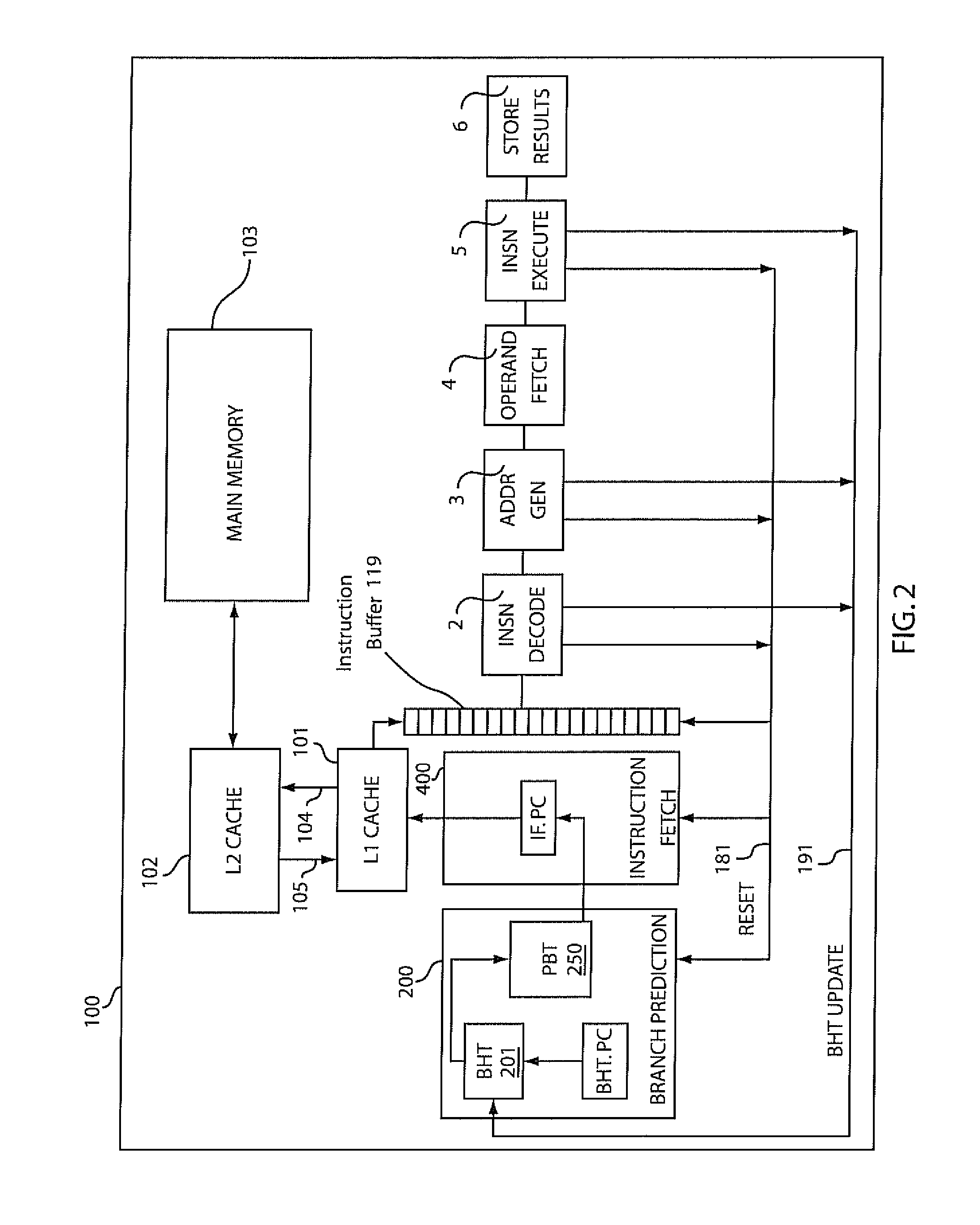
[0045] The present invention is directed to improving data flow in data processing systems. One aspect of the present invention includes a Context Look Ahead Branch History Table (BHT), which does not add hardware to a critical data flow path and, in fact, reduces the amount of hardware in the critical path. For purposes of illustrating the present invention, an analogy can be drawn to the relationship between a cache and main memory. Increasing the cache size is usually desirable, but not always practical because of limitations in chip area and cycle time restrictions. Instead of increasing the cache size, a second level cache (L2) may be added to the memory hierarchy to improve performance.

[0046] Unlike caches, the transfer from a second level BHT to a first level BHT needs to be performed in advance of its use. A cache like on-demand transfer from the second level BHT to the first level BET is not sufficient to insure timely arrival of data. All branch prediction information sav...


PUM


Abstract

A memory storage structure includes a memory storage device, and a first meta-structure having a first size and operating at a first speed. The first speed is faster than a second speed for storing meta-information based on information stored in a memory. A second meta-structure is hierarchically associated with the first meta-structure. The second meta-structure has a second size larger than the first size and operates at the second speed such that faster and more accurate prefetching is provided by coaction of the first and second meta-structures. A method is provided to assemble the meta-information in the first meta-structure and copy this information to the second meta-structure, and prefetching the stored information from the second meta-structure to the first meta-structure ahead of its use.

Description

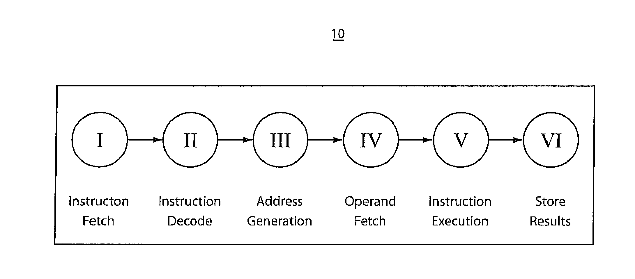
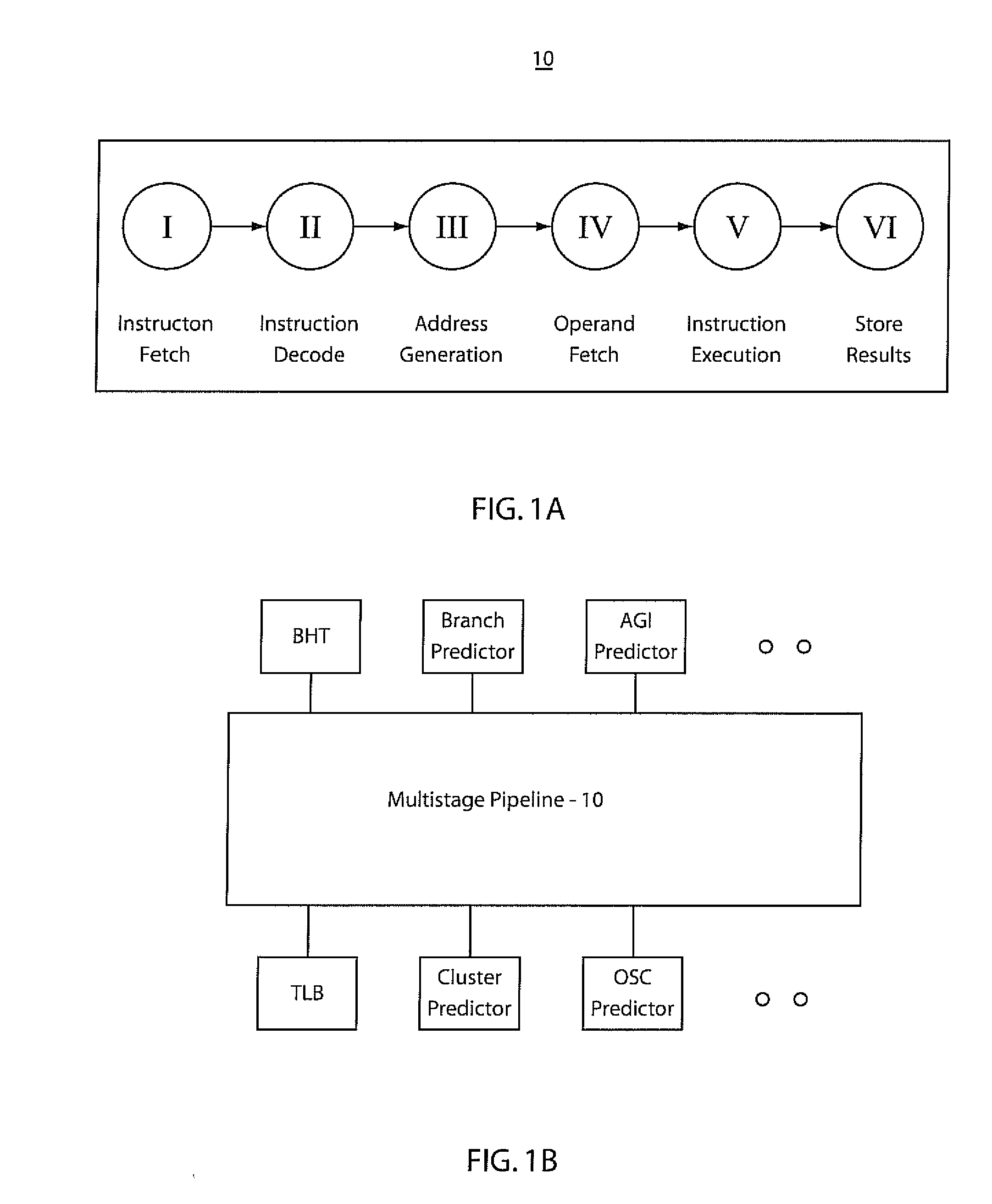
CROSS-REFERENCE TO RELATED APPLICATIONS [0001] This application is a continuation of co-pending U.S. patent Ser. No. 10 / 724,815, filed Dec. 1, 2003, which is incorporated by reference herein in its entirety.BACKGROUND OF THE INVENTION [0002] 1. Field of the Invention [0003] The present invention relates to data processing, and more particularly to prefetching of branch and other Meta information between hierarchical storage levels. [0004] 2. Description of the Related Art [0005] In most high performance processors, pipelining is used as a means to improve performance. Pipelining allows a processor to be divided into separate components where each component is responsible for completing a portion of an instruction's execution. [0006] Referring to FIG. 1A, an illustration of the major components that make up a typical processor's pipeline 10 are shown. The components include an instruction fetch (stage I), instruction decode (stage II), address generation (stage III), operand fetch (s...

Claims


Application Information

Patent Timeline
Patent Type & Authority Applications(United States)
IPC IPC(8): G06F9/00G06F9/38
CPCG06F9/3806
Inventor EMMA, PHILIP GEORGEHARTSTEIN, ALLAN MARKPRASKY, BRIAN R.PUZAK, THOMAS ROBERTSAHMED QURESHI, MOINUDDIN KHALILSRINIVASAN, VIJAYALAKSHMI
Owner INT BUSINESS MASCH CORP
Learn More