
Water supply channel for evenly wetting a hybrid dry cooler

a technology of water supply channel and hybrid dry cooler, which is applied in the direction of trickle coolers, stationary conduit assemblies, lighting and heating apparatus, etc. it can solve the problems of affecting the cleaning effect, so as to eliminate the influence of surface tension and hinder cleaning and maintenance

Inactive Publication Date: 2008-02-21
JAEGGIGUNTNER SCHWEIZ
View PDF11 Cites 3 Cited by
  • Summary
  • Abstract
  • Description
  • Claims
  • Application Information

AI Technical Summary

Benefits of technology

[0016]An object of the invention, is to provide water required for wetting a fin-heat exchanger across the full length and above the heat exchanger as a single, even film of water. It is a further object to largely eliminate the influence of the surface tension of the water on the water overflow edge, so that even if the surface has grease or dirt in some way, or if the overflow edge is not exactly horizontal or if there are slightly uneven sections, the water still flows evenly across the guide plate. Furthermore, if during re-feeding of the water in the supply channel waves are created, which disturbs the overflow, this can be avoided by suitable baffles. The delivery of water should not hinder cleaning and maintenance of the supply channel.SUMMARY OF THE INVENTION
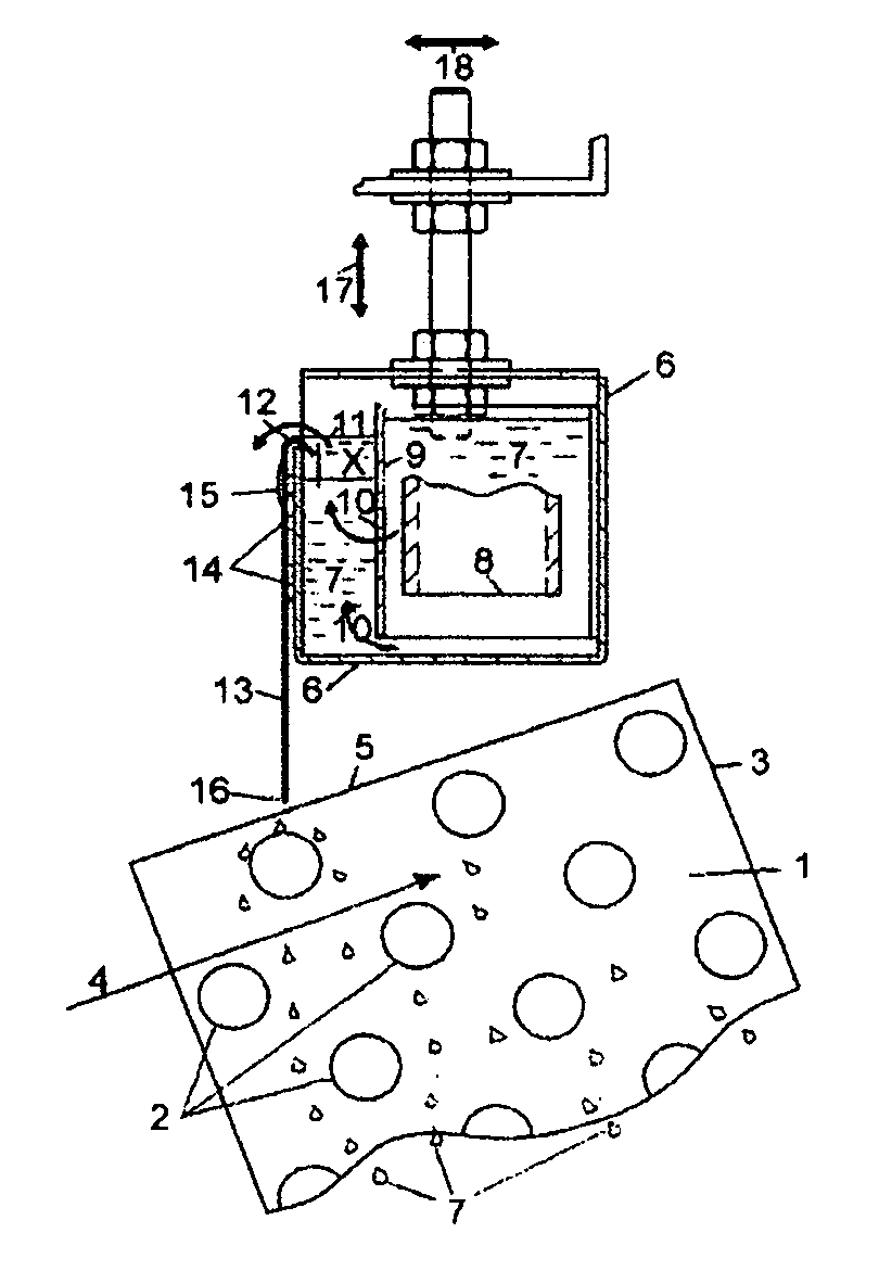
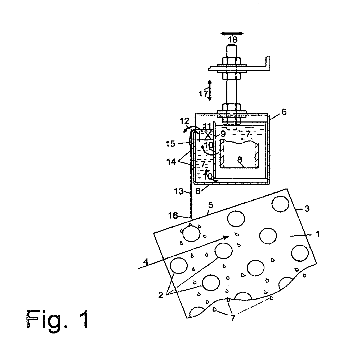
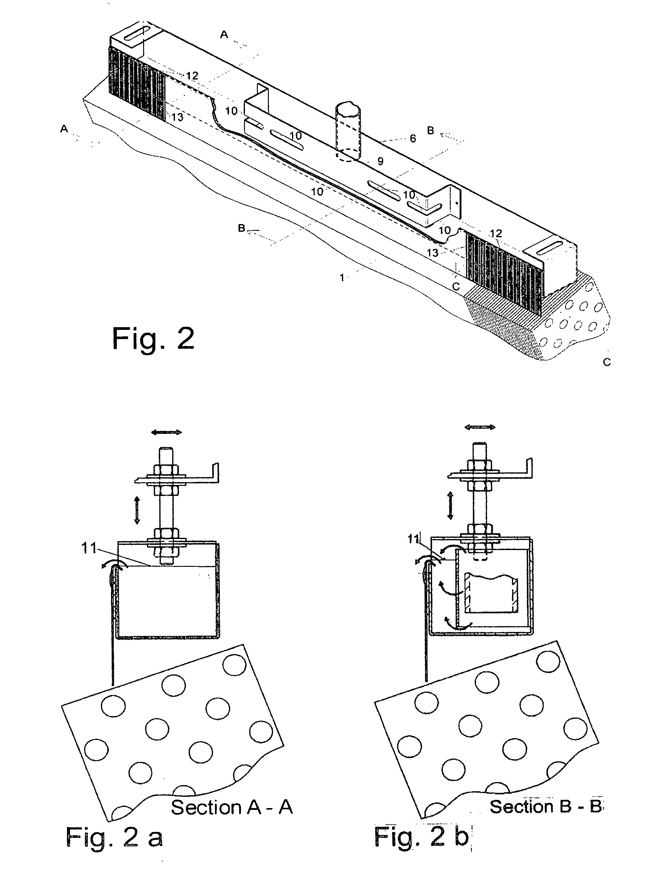
[0019]Openings stamped approximately in the middle of the baffle for the through flow of the water, may be in the forms of round holes or slits or have a geometric shape. The whole cross section of the opening is constructed large enough so that the quantity of water flowing through is approximately equal to the amount of overflow of the supply channel on the heat exchanger and thereby no, or very little, water flows over the overflow edge of the baffle. The supply channel has a free open side mounted at the back and can (for example by means of a water jet) be cleaned easily without dismantling any parts.
[0020]In order to achieve even transfer of the calmed water level in the supply channel to the guide plate and then to the heat exchanger, a linear shaped guide plate is fixed on the outer side of the supply channel in the direction of flow, which is curved in the region of the overflow in such a way that a small part of the guide plate projects beneath the surface of the water in the water supply channel. This curvature should have a specific radius so that the lines of stamped openings, which run through can be kept at the same height as much as possible. In this way the surface tension of the water on the overflow edge is largely broken and a type of suction effect is produced in the depth of the stampings, which enables an even overflow of the water.
[0021]In order to produce a discharge of wetting-water in the form of a film, from the guide plate to the heat exchanger, the guide plate must be at the highest point of the heat exchanger and must almost touch it. This avoids the water film being influenced by currents of air produced by the fan. Even at low flow velocities, the uneven geometric arrangement of an elementary formation of the water-droplet slit and water-droplet splitting louvers produces sufficient turbulence to increase the heat transfer coefficient in pure drying operation and the evaporation percentage during wetting.
[0023]Other advantages that result from higher air loading during wetting include a more economical operation of a connection in series of a drying cooler for purely sensible heat transfer with a hybrid (water-wettable) cooler for mainly latent heat emission, especially at high cooling-medium entry temperatures, a very large cooling range and use of the same fans for forced-air feeding through both heat exchangers. The same advantages also result during completely wetted operation of heat exchangers connected in series or in parallel.

Problems solved by technology

The greater the sag between two supports, as a consequence of changes in the weight of water, the more difficult it will be to achieve an even overflow.
Beneath these areas the fins remain dry and there is a loss of efficiency.
The manufacture and use of semicircular guide pipes for the “stream”—section is very difficult with the accompanying increase in length and is hardly ever used.
Between the supply channel and the fin set of the heat exchange, plates are installed to work against the sagging However, such plate installations usually hinder cleaning and maintenance.
There are further problems with fixing the guide plate, which is shaped with grooves, to the supply channel.
In the region of the rivets there is a slight increase in the flow, caused by raised material, which additionally hinders the overflow.
In addition, uncontrolled water can run between the wall of the supply channel, which can also lead to crevice corrosion.
Pasting on shaped guide plates with mounting adhesive bands initially provides a definite improvement, but has only a limited life.
Slight sagging of the supply channel cannot be adjusted out by this however.
In addition the life of the rubber profile is greatly reduced.
There are also further problems with the supply of water in the water supply channel.
This type of water re-feeding has the disadvantage that impurities in the water, which are larger than the discharge holes, will block them.
In addition, the cleaning of the water supply channels is made much more difficult, because the pipes which are lying in the supply channels must be dismantled for cleaning.
On the whole, the water supply described here is an even distribution of the water over the length but with regard to production and maintenance costs is fully unsatisfactory.

Method used


Image

  • Water supply channel for evenly wetting a hybrid dry cooler
  • Water supply channel for evenly wetting a hybrid dry cooler
  • Water supply channel for evenly wetting a hybrid dry cooler

Examples


Embodiment Construction

[0030]In accordance with FIG. 1 a state of the art hybrid heat exchanger 1 has several pipes 2, which run parallel to each other and which are located a distance apart from each other. The pipes 2 lie horizontal, which in FIG. 1 means vertical to the plane of the drawing. A stream of liquid is circulated through the pipes 2, whose temperature must lie above that of the ambient temperature.

[0031]On the pipes sit fins 3 along the length of the pipe which are located to increase the size of the airside heat exchange. Here it is above a compact heat exchanger whose fins 3 are drawn from several pipes 2. It could also be used where individual ribs are assigned to the individual pipes.

[0032]Above the upper face 5 of the fins 3, is located the water supply channel 6 of the wetting water 7, which is produced in large quantities, which can evaporate in the air current 4. The excess wetting water 7 is collected in a collection basin, which is not shown here, and is recycled by a pump to the s...


PUM


Abstract

A hybrid cooler with selectively applied water to one or more heat exchangers has one or more water feed channels above each heat exchanger to which water is to be applied constructed to provide a smooth film of water by a feed channel overflow edge and with means for suppression of waves, if any, in the channel.

Description

FIELD AND BACKGROUND OF THE INVENTION[0001]The present invention relates to hybrid coolers utilizing a combination of direct heat transfer via pipe / fin arrays and evaporative cooling and more particularly concerns the even supply of water from a water supply channel. The concept of “hybrid” here comes from the split operation method of the air-cooled heat exchanger, namely once without wetting the heat exchanger with water and for the other with wetting. Hybrid dry coolers can be wetted using water on the air side of the heat exchanger surfaces, in order to increase efficiency or to achieve temperatures of the cooling medium which are 4 to 5 K below the dry air temperature.[0002]European Patent No. EP 0428647 shows it is known to feed water for wetting to the air-side outer surfaces of the heat exchanger by an overflow from an open channel and over fitted with a guide plate and a semicircular, inner catalyst tube fitted above the cooling fins. In order to improve the flow of the wat...

Claims


Application Information

Patent Timeline
IPC IPC(8): F28D5/00F25B25/00
CPCF25B39/04F28F25/02F28D5/02F25B2339/041
Inventor BRENTROP, HANSJORG
Owner JAEGGIGUNTNER SCHWEIZ
Learn More