
External heat engine of the rotary vane type and compressor/expander

Inactive Publication Date: 2008-02-21
CARNAHAN ERIC SCOTT
View PDF7 Cites 32 Cited by
  • Summary
  • Abstract
  • Description
  • Claims
  • Application Information

AI Technical Summary

Benefits of technology

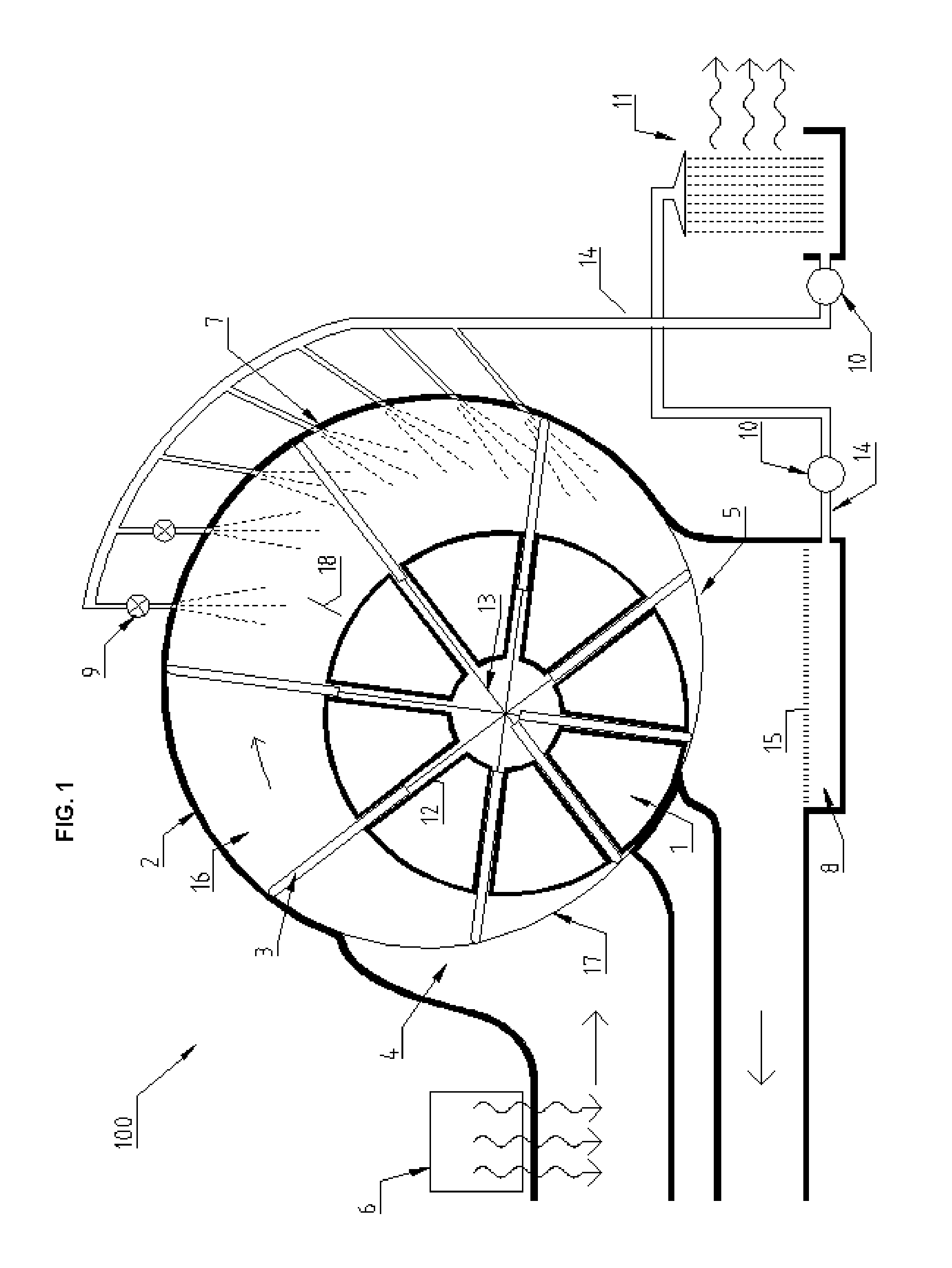
[0006]Accordingly, it is an object of this invention to provide an engine capable of effectively converting thermal energy contained within relatively low temperature hot gasses into mechanical energy at the lowest possible cost. The invention can be used in addition to or as a replacement for the ranking vapor compression cycle commonly used for such purposes.
[0008]After the gas is heated it enters the engine through the inlet port into the spaces between the engines vanes, rotor and housing. As the gas moves past the inlet port it enters the expansion section of the engine where the gas expands adiabatically to a sub-atmospheric pressure. Just before the gas leaves the expansion section a cooling liquid is injected into the gas through holes in the walls of the engine housing further reducing its temperature and pressure.
[0009]Next the gas leaves the expansion section of the engine it enters the compression section. Here more cooling liquid is injected into the gas, which absorbs heat generated by the compression process. This reduces the amount of work required to compress the gas back to atmospheric pressure. Finally, the working gas and the cooling liquid leave the engine through the outlet port at the bottom of the engine.

Problems solved by technology

However, heat engines that are designed to operate at high temperatures and high efficiencies typically cannot effectively or economically convert thermal energy from low temperature heat sources into other usable forms of energy.
However the ranking cycle does not efficiently harness thermal energy from gasses at temperatures above or below the boiling point of its working fluid.
However the high cost of manufacturing gas turbines has prevented such engines from being used on a large scale.

Method used


Image

  • External heat engine of the rotary vane type and compressor/expander
  • External heat engine of the rotary vane type and compressor/expander
  • External heat engine of the rotary vane type and compressor/expander

Examples


Embodiment Construction

[0020]In describing the preferred and alternate embodiments of the present invention, as illustrated in FIGS. 1-8, specific terminology is employed for the sake of clarity. The invention, however, is not intended to be limited to the specific terminology so selected, and it is to be understood that each specific element includes all technical equivalents that operate in a similar manner to accomplish similar functions.

[0021]Referring now to FIG. 1, illustrated therein is heat engine 100, having an outer housing 2 and a rotor 1 that rotates within the housing. Contained within the rotor 1 are a plurality of slots 12 and a plurality of sliding vanes 3 residing within the slots 12. The vanes 3 extend outwards to make contact with the inner walls of the housing 2.

[0022]Each vane 3 is connected to another vane 3 on the opposite side of the rotor 1 by one or more connecting linkages 13. The connecting linkages 13 that connect a pair of vanes 3 are horizontally offset from other connecting...


PUM


Abstract

A heat engine of the rotary vane type and thermodynamic cycle is disclosed. The engine converts thermal energy contained within relatively low temperature hot gasses into mechanical energy. The engine operates by expanding a hot gas to a sub-atmospheric pressure, cooling the gas at a roughly constant volume and then cooling the gas further while compressing it back to atmospheric pressure. Possible sources of hot gasses for powering the engine include exhaust gasses from other engines and air heated by solar collectors. A novel compressor and expander comprised of the primary components of the engine is also disclosed.

Description

BACKGROUND OF THE INVENTION[0001]Heat engines that convert thermal energy into mechanical energy by cycling a working fluid through a suitable thermodynamic cycle have been around for a very long time and come in countless varieties. To maximize efficiency heat engines are typically designed to heat their working fluid to a high temperature. The higher the temperature reached by the working fluid the more efficient the engine can become.[0002]However, heat engines that are designed to operate at high temperatures and high efficiencies typically cannot effectively or economically convert thermal energy from low temperature heat sources into other usable forms of energy.[0003]Given the rising cost of fuel and a relative abundance of low cost and environmentally friendly low temperature heat sources, the economic viability of an engine that can effectively harness the energy of low temperature heat sources is greater than ever.[0004]The Ranking Vapor Compression cycle if often used to ...

Claims


Application Information

Patent Timeline
IPC IPC(8): F01C19/02F01C19/00F01K23/06
CPCF01C1/3442F01C21/04F01C21/0881F01C21/0836F01C21/06
Inventor CARNAHAN, ERIC SCOTT
Owner CARNAHAN ERIC SCOTT
Learn More