
Axial Gap Type Superconducting Motor

a superconducting motor and axial gap technology, applied in the direction of superconductor devices, magnetic circuit rotating parts, magnetic circuit shape/form/construction, etc., can solve the problems of motor inevitably increasing, reducing energy efficiency, increasing weight, etc., and achieve high efficiency, large current, and no copper loss

Inactive Publication Date: 2008-02-14
SUMITOMO ELECTRIC IND LTD +1
View PDF17 Cites 8 Cited by
  • Summary
  • Abstract
  • Description
  • Claims
  • Application Information

AI Technical Summary

Benefits of technology

[0038] As clear from the above description, according to the invention, a superconductive material is used for the field bodies and / or the armature coils of the axial gap type motor. Thus, a large current can be applied with high efficiency, without a copper loss. Further, high-output motor torque can be obtained, and the size and weight of the motor can be reduced. Further, since the stators are disposed in the axial direction of the rotor as the axial gap type structure, the size of the motor can be reduced, and noises caused by rotation can also be reduced.
[0039] In addition, the flux collectors of magnetic bodies are disposed in the coil hollow parts. Therefore, the magnetic flux of the coils can be strengthened, which makes it possible to realize a high-output motor. Further, the size and weight of the motor can be reduced. Providing flux collectors contributes to specification of the magnetic flux directions, and a reduction in leakage magnetic flux.

Problems solved by technology

Further, in order to increase output, the size of a motor inevitably increases so that the weight thereof increases.
Further, if the amount of a current increases, the energy efficiency is lowered due to a copper loss or the like.

Method used


Image

  • Axial Gap Type Superconducting Motor
  • Axial Gap Type Superconducting Motor
  • Axial Gap Type Superconducting Motor

Examples


first embodiment

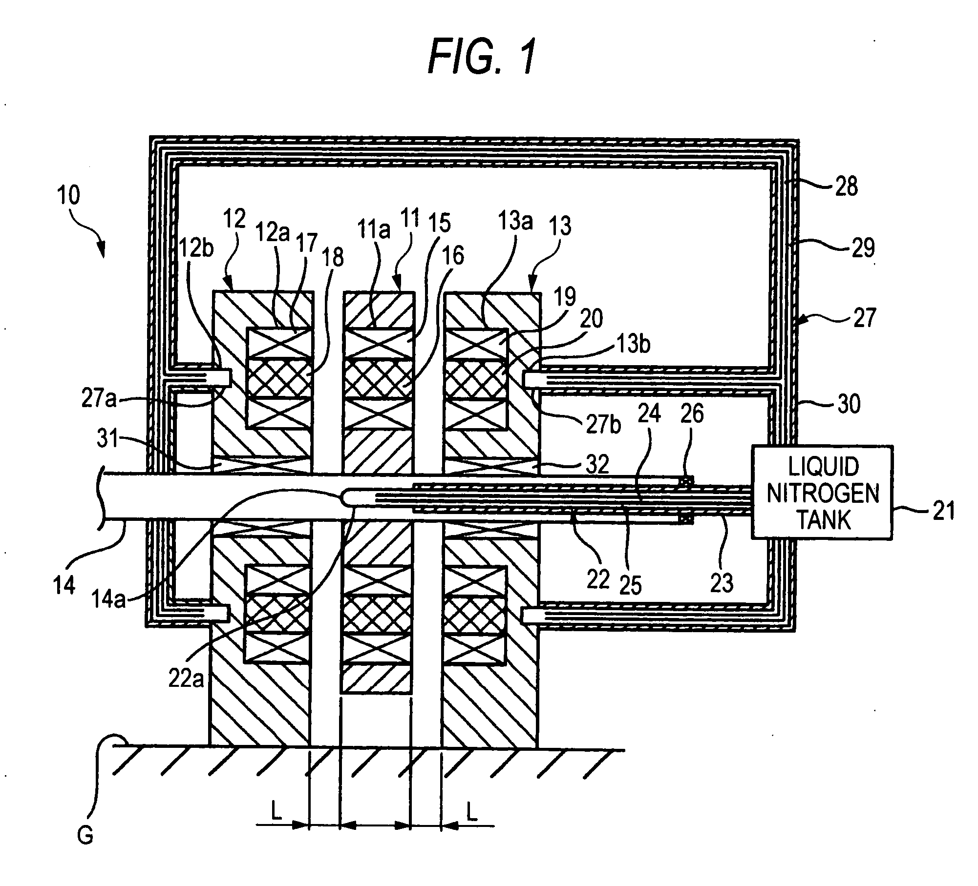
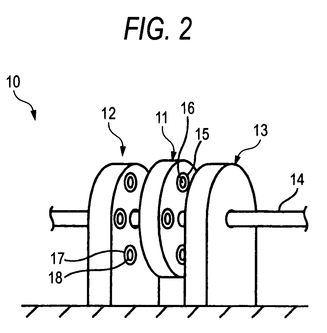
[0058]FIGS. 1 and 2 show an axial gap type superconducting motor 10 according to the invention. The axial gap type superconducting motor 10 has a pair of stators 12 and 13 disposed to face each other on both sides of a rotor 11 in an axial direction of the rotor 11 fixed to a rotary shaft 14. The rotary shaft 14 fixed to the rotor 11 is hung so as to pass through bearings 31 and 32 of the stators 12 and 13.

[0059] The rotor 11 is formed in a disk shape, and the rotary shaft 14 is fixed to the rotor 11 so as to pass through the center thereof. The rotor 11 has a plurality of coil attachment holes 11a, which are provided at regular intervals in a peripheral direction on the outer peripheral side thereof, and a plurality of field coils 15 buried in the coil attachment holes 11a, the field coils 15 being made of a superconductive material. As such, the plurality of field coils 15 are attached at regular intervals in a peripheral direction around the axis of the rotor such that the magnet...

second embodiment

[0071] Next, the invention will be described.

[0072] As shown in FIG. 3, a difference from the first embodiment is that flux collectors 35 disposed in hollow parts of the field coils 15 of the rotor 11 are buried so as not to project from the end surfaces of the field coils 15.

[0073] If this configuration is adopted, the flux collectors 35 do not project from the leading end surfaces of the field coils 15. Thus, an attraction force caused by a magnetic force is hardly generated between the stators 12 and 13 during assembling, etc. Further, any collision between the rotor 11 and the stators 12 or 13 does not occur. Therefore, positioning is easily performed while a gap is maintained at a set distance.

third embodiment

[0074] Next, the invention will be described.

[0075] As shown in FIG. 4, a difference from the first embodiment is that air gaps S are provided in the hollow parts of the armature coils 17 and 19 of the stators 12 and 13.

[0076] If this configuration is adopted, magnetic bodies are not present in the hollow parts of the armature coils 17 and 19 facing the flux collectors 16 of the rotor 11, and an attraction force caused by a magnetic force between field bodies is not generated during assembling, etc. Thus, positioning can be easily performed while the gap between the rotor 11 and the stators 12 or 13 is maintained at a set distance.

[0077] In general, when flux collectors are disposed in hollow parts of coils, a magnetic field is strengthened. As shown in FIG. 5, however, a magnetic flux does not almost increase after a current exceeds a certain value. Rather, when flux collectors are not provided, the magnetic field tends to be strengthened. That is, the axial gap type superconduct...


PUM


Abstract

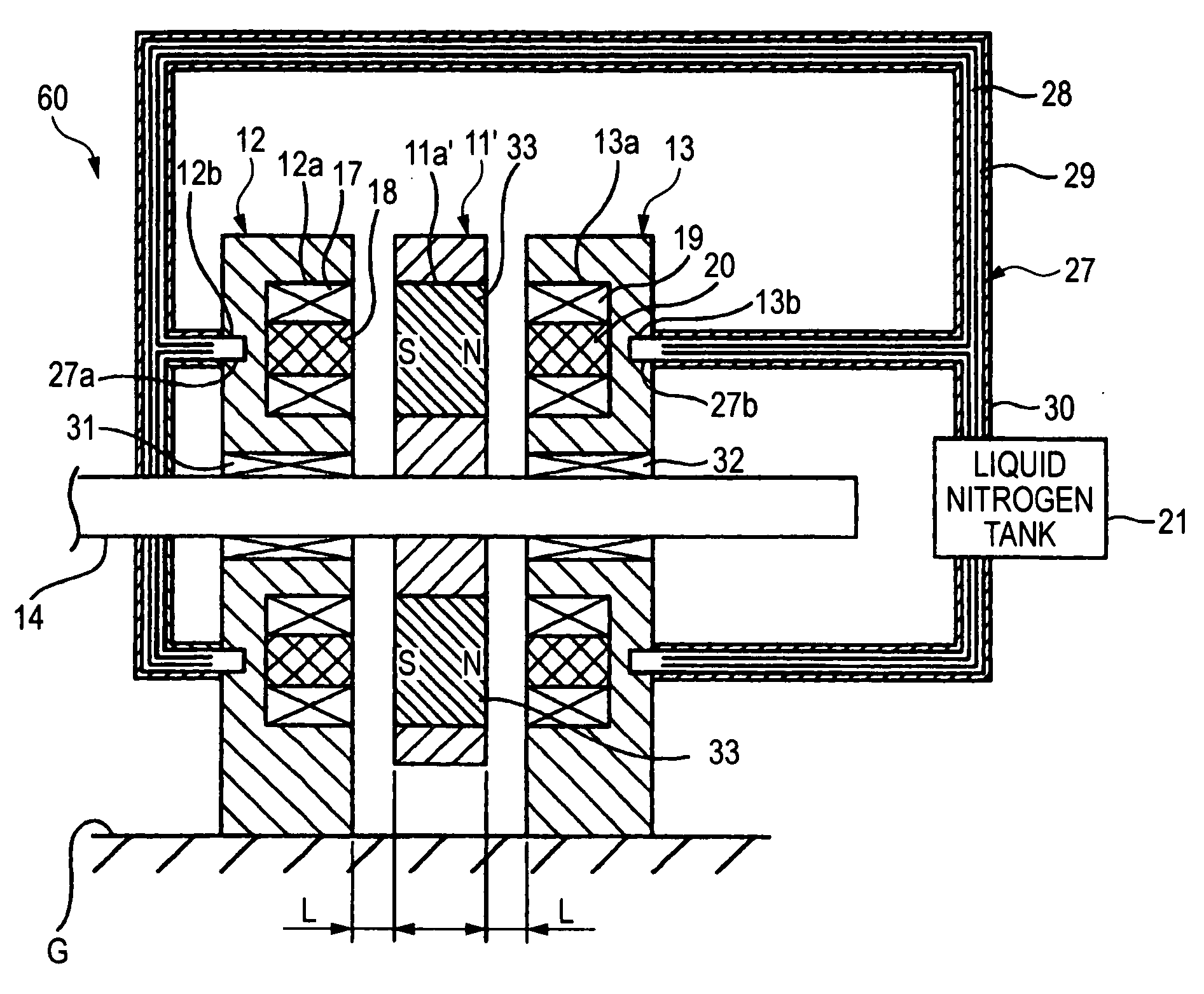
Stators 12 and 13 are disposed with required air gaps in an axial direction of a rotor 11 so as to face each other, a plurality of field bodies 15 or permanent magnets 33 are disposed in the rotor 11, and a plurality of armature coils 17 and 19 are disposed in the stators 12 and 13 around the axis. At least one of the field bodies 15 or permanent magnets 33 and the armature coils 17 and 19 are formed from a superconductive material such that their magnetic flux directions are directed to the axial direction.

Description

TECHNICAL FIELD [0001] The present invention relates to an axial gap type superconducting motor, and more specifically, to a high-torque motor which is used as a driving source of cars and ships. RELATED ART [0002] Conventionally, there are provided a radial gap type motor and an axial gap type motor as motors. As the radial gap type, a motor in which a rotor provided in a hollow part of a stator having an annular cross-section such that the magnetic flux directions of coils are directed to a radial direction is widely and generally used. Meanwhile, the axial gap type motor, as disclosed in Japanese Unexamined Patent Application Publication No. 2004-140937, has stators disposed to face each other in the axial direction of a rotor such that the magnetic-flux directions of coils are directed to the axial direction. [0003] In the conventional axial gap type motor, however, permanent magnets or coils such as copper wires are used for a magnetic field, and copper wires are used for armat...

Claims


Application Information

Patent Timeline
Patent Type & Authority Applications(United States)
IPC IPC(8): H02K55/04H02K1/27H02K16/00
CPCH02K55/04Y02E40/60
Inventor OKAZAKI, TORUOHASHI, SHINGOSUGIMOTO, HIDEHIKOTAKEDA, TOSHIO
Owner SUMITOMO ELECTRIC IND LTD
Learn More