
Fuel cell fuel processor with hydrogen buffering and staged membrane

a fuel processor and fuel cell technology, applied in the field of fuel cell systems, can solve the problems of limited use of space-constrained fuel cell applications, excessive heat generation, and substantial yield of hsub>2/sub

Inactive Publication Date: 2008-02-14
EXXON RES & ENG CO
View PDF13 Cites 92 Cited by
  • Summary
  • Abstract
  • Description
  • Claims
  • Application Information

AI Technical Summary

Benefits of technology

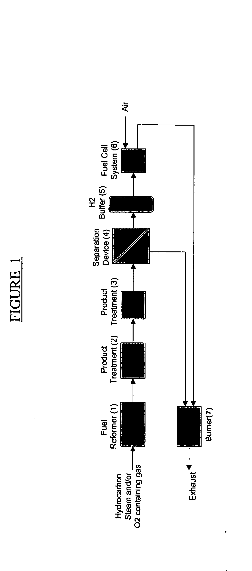
The patent describes a fuel cell system that includes a fuel cell, a device for processing fuel to produce hydrogen, and a buffer to store excess hydrogen for use by the system during start-up or when needed by the fuel cell. The system is designed for space-constrained applications such as vehicles. The technical effect is a more efficient and flexible fuel cell system that can produce energy in a compact space and at a high efficiency.

Problems solved by technology

The large size of such conventional steam reformer is one factor that limits its use in space constrained fuel cell applications such as on board vehicles.
However, gas-phase reaction kinetics tend to over-oxidize some of the feed, resulting in excessive heat generation and substantial yield of H2O, CO2, unreacted hydrocarbons and soot.
In autothermal reforming processes a source of oxygen such as air is employed which results in a nitrogen-diluted synthesis gas that renders the gas less suitable for fuel cell use in space constrained applications.
However, these patents describe a process that operates at very low productivity, with space velocities of around 100 hr−1 (as C1-equivalent).
One consequence of Sederquist's low space velocity is that resulting high heat losses impede the ability of this technology to achieve the theoretical high efficiency.
As will be readily appreciated the incorporation of any fuel processing scheme in a fuel cell system that involves converting hydrocarbon fuels to hydrogen for the purpose of fueling a fuel cell, poses problems associated with start-up and transient performance.

Method used


Image

  • Fuel cell fuel processor with hydrogen buffering and staged membrane
  • Fuel cell fuel processor with hydrogen buffering and staged membrane
  • Fuel cell fuel processor with hydrogen buffering and staged membrane

Examples


example 1

Power During Start-Up

[0088]FIG. 7 shows the maximum time over which hydrogen can be drawn from a hydrogen buffer, as a function of fuel cell power output. In this example a hydrogen buffer of size 10 liters storing hydrogen at 15 atm is used in conjunction with a 50% efficient fuel cell system having 50 kWe maximum power and operating at ambient pressure. This time reflects the duration that the fuel cell can be operated before hydrogen input from the reforming system is required, and thus represents the time available for processor startup. The available time for processor start-up and hydrogen rich gas production will vary with the size of the buffer and the maximum pressure at which the hydrogen gas is stored. For larger buffer size and / or higher storage pressures available start-up time will increase at a given initial sustained power output from the fuel cell system.

example 2

Turndown and Transients

[0089] In this example, the hydrogen demand of a fuel processor (˜0.9 g / sec H2 maximum output), that is connected to a fuel cell system for operating, over automobile drive-cycle is moderated via the hydrogen buffer of 10 liter size capable of storing hydrogen at pressures up to 20 bars. The fuel processor is assumed to take 30 seconds to heat-up and start producing hydrogen. It is further assumed that the fuel processor is capable of operating only in two modes, ON (full power or maximum H2 output) and OFF (zero power or zero H2 output). The hydrogen demand from the fuel cell is met by supplying hydrogen from the buffer and as the buffer pressure falls below certain set value (4 bars), the fuel processor is turned ON to produce H2 at its 100% rated value and fill the buffer. Once the buffer pressure builds up to a certain pressure (18 bars) the fuel processor is turned OFF. FIG. 8 shows hydrogen supply to buffer from the processor and demand from the fuel ce...


PUM

PropertyMeasurementUnit
thickaaaaaaaaaa
thickaaaaaaaaaa
temperatureaaaaaaaaaa

Abstract

A fuel cell system is provided which includes a hydrocarbon fuel processor for generating hydrogen for use in a fuel cell. The system further includes a hydrogen buffer for storing a portion of the hydrogen generated by the fuel processor. The system further includes a staged hydrogen selective membrane providing pressurized hydrogen to the buffer. This stored hydrogen may then be used during start-up of the system in a number of ways, such as feed for the fuel cell, or when the fuel processor output is temporarily less than that required by the operating demand of the fuel cell.

Description

[0001] This application is a Continuation-in-Part of U.S. Ser. No. 10 / 336,208 filed Jan. 20, 2006 of Provisional U.S. Ser. No. 60 / 652,074 filed Feb. 11, 2005.FIELD OF THE INVENTION [0002] The present invention relates to fuel cell systems incorporating a hydrocarbon fuel processor for generating hydrogen for use in a fuel cell. In particular the present invention provides improvements in the start-up and transient performance of such systems, especially those designed for use in confined space applications such as “on board” vehicle applications. BACKGROUND OF THE INVENTION [0003] Hydrogen may be produced from hydrocarbons in a fuel processor such as a steam reformer, a partial oxidation reactor or an auto-thermal reformer and a fuel cell system incorporating such hydrocarbon fuel processors have been proposed. [0004] In the case of a steam reforming, steam is reacted with a hydrocarbon containing feed to produce a hydrogen-rich synthesis gas. The general stoichiometry, illustrated ...

Claims


Application Information

Patent Timeline
Patent Type & Authority Applications(United States)
IPC IPC(8): H01M8/04H01M8/06G06F1/18G06F1/20
CPCG06F1/184G06F1/20G06F1/187H01M8/0612Y02E60/50H01M8/04225H01M8/04H01M8/06H01M8/04302
Inventor BERLOWITZ, PAUL J.AGNIHOTRI, RAJEEVHERSHKOWITZ, FRANKRADOS, NOVICA S.FREDERICK, JEFFREY W.CALABRO, DAVID C.PARTRIDGE, RANDALL D.
Owner EXXON RES & ENG CO
Learn More