Cutting Insert Provided With Structured Surfaces

a cutting insert and structured surface technology, applied in the field of cutting inserts, can solve problems such as chip breakage, and achieve the effect of high quality of machined surface and advantageous cutting

Inactive Publication Date: 2008-02-07
BOEHLERIT GMBH & CO KG
View PDF29 Cites 9 Cited by
  • Summary
  • Abstract
  • Description
  • Claims
  • Application Information

AI Technical Summary

Benefits of technology

[0015] Furthermore, it was found that advantageously the heat transfer into the cutting insert is reduced and the durability of a coating is also increased and the abrasion in the area of the cutting face close to the cutting edge is reduced.
[0023] For particularly ductile materials, it can be particularly advantageous in cutting if the fine structure is formed as a superstructure on the cutting face of a cutting insert, which cutting face is formed with step chip breakers or chip-breaker elevations. There can thus be beating effects in the mechanical action on the chip being produced which promote the formation of short chips despite unfavorable material prerequisites.

Problems solved by technology

The reason for this has not yet been sufficiently explained in scientific terms, however, it can be assumed that the fine structure of the cutting faces leads to compressive stresses and deformations in the chip being produced, which lead to the initiation of chip breaks, even with tough material of the workpiece.

Method used


Image

  • Cutting Insert Provided With Structured Surfaces
  • Cutting Insert Provided With Structured Surfaces
  • Cutting Insert Provided With Structured Surfaces

Examples


Embodiment Construction

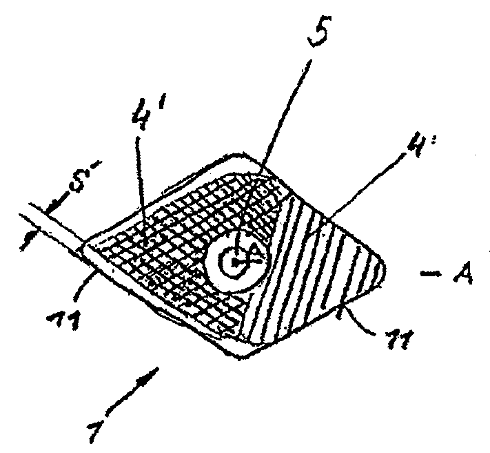
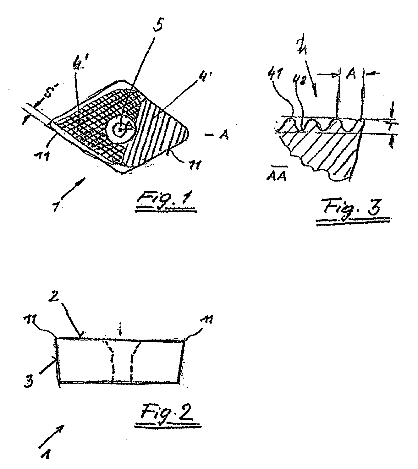
[0033]FIG. 1 shows in a schematic representation an indexable insert 1 according to the invention that can be fixed from above through a bore 5 on a clamp-type tool holder. FIG. 2 shows a view of the indexable insert 1 with cutting edges 11, free (or lateral) surfaces 3 and a cutting face 2.

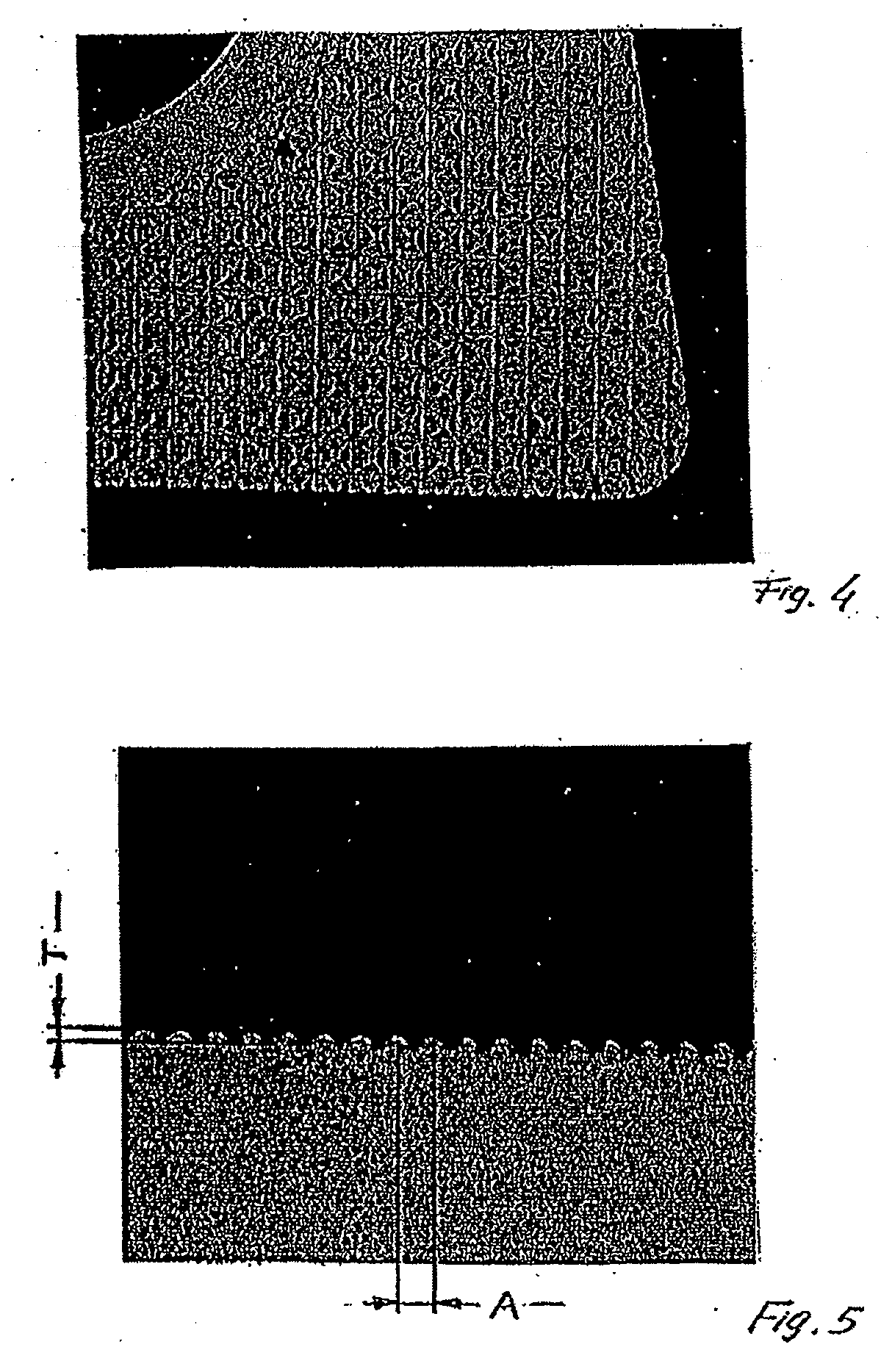
[0034]FIG. 1 shows fine structurings 4, 4′ of the cutting face 2 of the indexable insert 1 in diagrammatic form. On the right of the cutting face 2 an essentially linear or wavy fine structure 4 extends up to a cutting edge 11. FIG. 3 shows in a partial sectional representation AA of a cutting corner towards the mounting bore 5 that the fine structure 4 has convex areas 41 and concave areas 42, which areas are respectively spaced apart by a distance A. A depth of the fine structure T is characterized by the perpendicular distance T between the highest elevation of the convex area 41 and the base of the concave area 42.

[0035] A fine structure 4′ formed by intersecting, respectively linear concav...


PUM

PropertyMeasurementUnit
Lengthaaaaaaaaaa
Lengthaaaaaaaaaa
Lengthaaaaaaaaaa

Abstract

Cutting insert for tools for cutting workpieces or objects, including at least one cutting edge, at least one lateral surface, and at least one cutting face comprising a fine structure having convex and concave areas. Additionally, the convex and concave areas, have a depth T and are respectively spaced apart from one another by a spacing A greater than 0.1 mm and less than 1.0 mm.

Description

CROSS REFERENCE TO RELATED APPLICATIONS [0001] The present application is a National Stage Application of International Application No. PCT / AT2005 / 000219 filed Jun. 21, 2005, which published as WO 2006 / 007607 A1 on Jan. 26, 2006, the disclosure of which is expressly incorporated by reference herein in its entirety. Further, the present application claims priority under 35 U.S.C. § 119 and § 365 of Austrian Application No. A 1257 / 2004 filed Jul. 22, 2004.BACKGROUND OF THE INVENTION [0002] 1. Field of the Invention [0003] The invention relates to a cutting insert, in particular an indexable insert, preferably of hard metal or cement for tools for cutting workpieces or objects with at least one cutting edge with free surface(s) and / or lateral surface(s) and at least one cutting face. [0004] 2. Discussion of Background Information [0005] In a modern machining or in a modern cutting procedure with high capacity of workpieces of metal, alloys or polyphase materials, tools are used with cu...

Claims


Application Information

Patent Timeline
IPC IPC(8): B26D1/00B23B27/14C23C16/02
CPCB23B27/143B23B2200/081B23B2200/083Y10T407/23B23B2200/321B23B2200/323B23B2200/086
Inventor PITONAK, REINHARDKIPPERER, KARLWEISSENBACHER, RONALDUDIER, KLAUS
Owner BOEHLERIT GMBH & CO KG
Why Eureka
Try Eureka